Physical Features
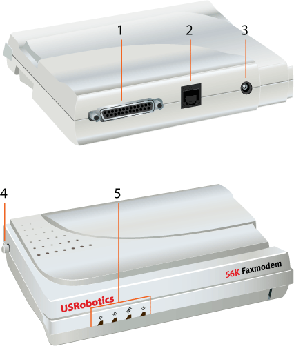
- Serial port connects the modem to your computer.
- Telephone port connects the modem to your phone line.
- Power port connects the modem to a power source.
- Power switch turns the modem on and off.
- LEDs indicate the status of the modem and the data being transferred. For more information about these indicators, see the table below.
| LED |
Name |
State |
Condition |
| RD |
Receive Data |
Blinking |
Receiving data |
| SD |
Send Data |
Blinking |
Sending data |
| PWR |
Power |
On |
Receiving power |
| CD |
Carrier Detect |
On |
Receiving a valid data signal from a remote modem; data transmission is possible.
OR
CD override is ON (&C0). |
Modulation Schemes
- ITU-T V.92
- ITU-T V.90
- ITU-T V.34+
- ITU-T V.34
- ITU-T V.32bis
- ITU-T V.32
- ITU-T V.22bis
- ITU-T V.22
- ITU-T V.23
- Bell 212A
Error Control and Data Compression Schemes
- ITU-T V.42
- ITU-T V.42bis
- MNP 2-5
- ITU-T V.44
Fax Modulation Schemes
- ITU-T V.17
- ITU-T V.29
- ITU-T V.27ter
- ITU-T V.21
Fax Standards
- EIA 578 Class 1 FAX
- EIA 592 Class 2.0 FAX
Downstream Link Rates (V.90/V.92)
56000, 54666, 53333, 52000, 50666, 49333, 48000, 46666, 45333, 44000, 42666, 41333, 40000, 38666, 37333, 36000, 34666, 33333, 32000, 30666, 29333, 28000
Upstream Link Rates (V.92-PCM Upstream)
48000, 46666, 45333, 44000, 42666, 41333, 40000, 38666, 37333, 36000, 34666, 33333, 32000, 30666, 29333, 28000
Upstream Link Rates (V.90)
31200, 28800, 26400, 24000, 21600, 19200, 16800, 14400, 12000, 9600, 7200, 4800
V.34+ Link Rates
33600, 31200, 28800, 26400, 24000, 21600, 19200, 16800, 14400, 12000, 9600, 7200, 4800
V.32bis Link Rates
14400, 12000, 9600, 7200, 4800
Additional Link Rate
2400, 1200, 300
Fax Link Rates
14400, 12000, 9600, 7200, 4800, 2400
DTE Rates
115200, 57600, 38400, 19200, 9600, 2400, 1200, 300