This topic describes each page of the Web User Interface and provides basic instruction for using each page.

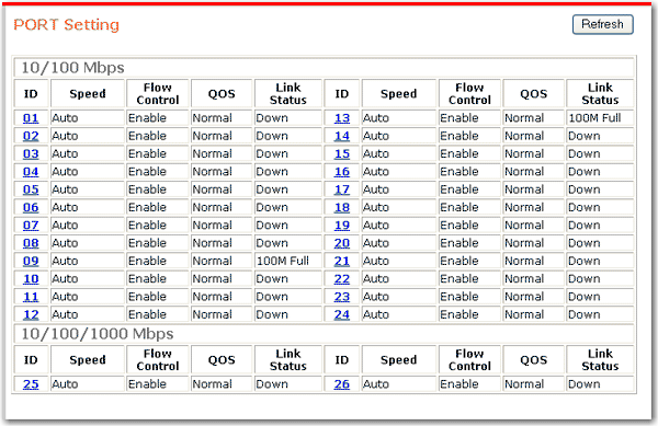
The Port Setting page shows the statuses of all ports and provides links to their flow control settings.
To update the status, click Refresh.
To set the speed, flow control, or QoS priority for a port:
Click the port ID number.
The settings for the selected port appear:
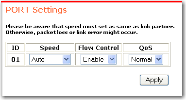
Select the values that you want for the port:
Speed/Disable has six modes: 100M Full, 100M Half, 10M Full, 10M Half, Auto, and Disable.
Flow Control determines whether or not the switch will be handling flow control. To avoid data transfer overflow, set flow control to Enable. If you do not want the switch to handle flow control, select Disable.
QoS sets the priority for the port. If you select High, the port will have 4 times the priority of ports for which you select Normal.
Click Apply.

By default, all ports on the participate in a single group, or VLAN, designated with the ID 01. You can group the ports differently so that each group acts as a separate VLAN. A port can only communicate with other ports in the same VLAN. Consequently, a port that does not participate in any VLAN cannot communicate with any other port on the switch. However, a port can participate in multiple VLANs and thereby have access to the resources in all of the VLANs in which it participates.
Any device connected to a port becomes a member in all VLANs in which the port participates. The device is not required to insert VLAN tags to outgoing traffic.
Note that the trunking function depends on VLANs. If a VLAN has a trunked port as a member, all ports on the same trunk must also be members of the VLAN.
To add a VLAN:
Click Add Group.
The VLAN Setting page appears, and the ID number is assigned automatically:
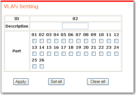
Enter a unique VLAN description and select the ports that are to participate in the new VLAN.
To help you select ports, Set all selects all ports and Clear all clears all selections.
Click Apply.
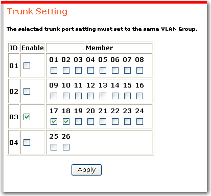
The trunk function lets you connect one USRobotics to another for the purpose of increasing bandwidth. You can define up to 4 trunks with predefined trunk ID numbers and predefined member sets.
All ports in a trunk must participate in common VLANs. For example, if trunk 03 contains ports 17 and 18 as shown above, port 17 must participate in every VLAN in which port 18 is a member and vice-versa.
Make sure that the ports to be used for trunking participate in the same VLAN.
In the trunking function, Enable the group for trunking.
Select the ports to be used for trunking and click Apply.
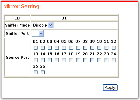
Port mirroring forwards a copy of each packet from one port of a network switch to another port where the packet can be studied. Based on the results of this study, you can alter switch performance if necessary. To enable port mirroring:
Select a Sniffer Mode to determine whether transmitted packets or received packets are to be captured:
TX mirrors the packets transmitted from the source ports.
RX mirrors the packets received by the source ports.
Both mirrors packets transmitted through the source ports in either direction.
Assign a Sniffer Port to which the packets will be sent. Depending on the amount of traffic being mirrored, sniffer port may not be able to handle all of the data that it receives. You can minimise the loss of captured data by using one of the gigabit ports as the sniffer.
Select each Source Port from which to copy packets.
Click Apply.
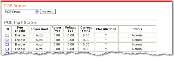

The PoE Status page displays the PoE setting of each port and the power settings of the switch. From this page, you can change the PoE settings of each port and you can set a trap to capture information when the powered devices use a specified percentage of the power available on the switch.
To change the PoE settings of a port, click the port number in the ID column of the PoE Port Status table.
To set the power trap, select POE System Setting from the dropdown list.
To update the status, click Refresh.
The System Power Status reports the following information:
System Budget Power—The amount of PoE power that the switch can supply.
Support Total Power—The amount of power being drawn by powered devices.
Remainder Power—System Budget Power minus Support Total Power.
The ratio of system power supply—Support Total Power / System Budget Power
You can determine which of ports 1–24 will provide power via PoE, and you can limit the amount of power available to the powered device on each PoE port. To protect the switch and the connected device, the switch will disable the PoE function of a port when the power exceeds the limit that you specify. To inform you of the condition, the status page will report the link status for the port as overcurrent.
When you select a port ID from the PoE Port Status table, the following page appears:
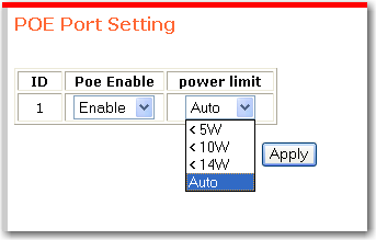
To enable PoE on the port,
Select Enable.
Select a power limit. The unit of measure is watts. Auto sets the power limit based on the classification of the powered device. The switch determines the classification based on the current of the powered device.
Click Apply.
To disable PoE on the port,
Select Disable.
Click Apply.
You can force a trap event to occur when PoE devices connected to the switch use more than a specified percentage of the available power. The percentage that you specify is known as the system power threshold, and can be set on the POE System Setting page:
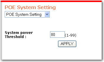
To set the threshold that :
In System power Threshold, enter the threshold percentage.
Click APPLY.
Note: When the switch does not have enough power for all the connected PoE devices, it prioritses by port number: the lower the number, the higher the priority. To ensure that your most important PoE devices are always powered, connect them to ports with low numbers.
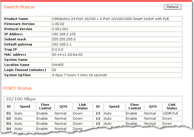
The status page displays the status of the port, VLANs, trunks, and mirroring. To update the status, click Refresh.
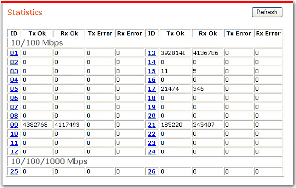
The statistics page shows performance statistics for each port on the switch.
To update the statistics, click Refresh.
To reset all counters to zero, click Clear Counters.
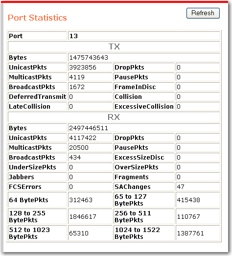
To see more detail for a port, click its port number. The port statistics page appears:
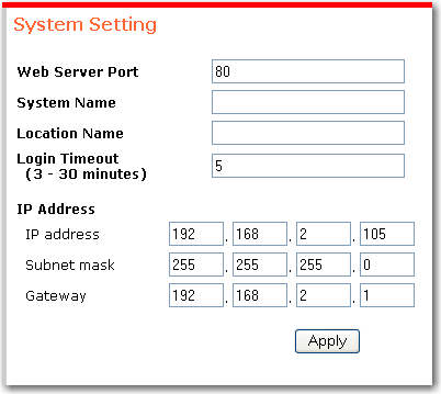
System settings include both descriptive information that makes it easy for you to identify a specific switch and addressing information, which determines the subnet of which the switch is a member.
System Name and Location Name are descriptive terms for your use; they have no bearing on the operation of the switch.
Login Timeout determines how long the can remain idle before requiring you to re-enter the password for access.
IP Address, Subnet Mask, and Gateway are manually assigned.
Remember to click Apply after entering any changes.
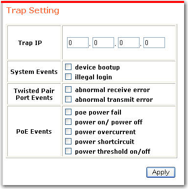
The sends traps for the selected events to the specified IP address. If you are using a Windows operating system, you can view the traps through the monitor list or View menu in the .
Following are the events that can be trapped:
| Event Name | Event |
|---|---|
| device bootup | when the switch boots up |
| illegal login | a user tries to log in and uses the wrong password |
| abnormal receive error | 50 error packets are received within 10 seconds |
| abnormal transmit error | 50 error packets are sent within 10 seconds |
| poe power fail | the port's power source fails |
| power on/ power off | the port's power turns on or off |
| power overcurrent | the port's power is overcurent |
| power shortcircuit | the port's power circuit is short |
| power threshold on/off | the system power supply is larger than or smaller than the system power threshold setting |
To set the traps:
In Trap IP, Enter the IP Address of the computer that is running the .
Select the kind of trap that you want to set.
Click Apply.
Use the to add the switch to the monitor list.
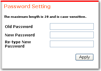
The password is required to make changes to the switch configuration through either the or the . USRobotics recommends that you change the password from its default of in order to prevent unauthorised changes to your configuration. To change the password:
Enter the Old Password.
Enter the New Password.
In Re-type New Password, enter the new password again.
Click Apply.
If you forget your password, you must reset the switch to its factory default settings by pressing the RESET button on the switch. After resetting the switch, you will have to reapply all of your configuration settings either manually or by restoring them from a backup.
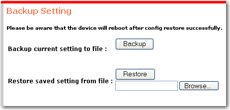
You can save your configuration settings to a file. If you ever need to reset the switch to its factory defaults, you can then restore your settings from the backup file so that you do not have to re-apply them manually. Restoring settings from a backup file does not override the current password.
To back up your configuration:
Click Backup.
When prompted to save the file, click Save.
Browse to the folder in which you want the file saved and click Save.
To restore your configuration:
In Restore saved setting from file type the file name or browse to your backup file.
Click Restore.
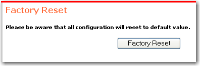
You can use the to reset the switch to its factory defaults.
Note: After successfully resetting the switch, your computer will lose connectivity to the switch unless the computer is in the same subnet as (the default IP address of the switch).
To reset the switch, click Factory Reset.