Make sure that your computer is not connected to a port in the range 9–16 or you will lose connectivity when you complete the next step.
All ports that share any VLAN in common with the trunking ports can use the trunk. To ensure that no unwanted ports can use the trunk, ports 9–16 must be removed from any VLAN shared with other ports. By default all ports on the belong to VLAN 01.
To make sure that the other ports in VLAN 01 cannot use the trunk, remove ports 9–16 from VLAN 01 (and any other VLAN that they share with other ports) as shown:
In the menu of the Web User Interface, select IEEE 802.1Q VLAN Setting :
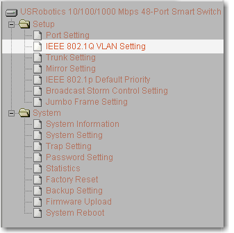
Select VID 01:

Select Not Member for ports 09–16, and click Apply:
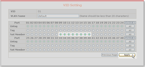
VLAN 01 no longer includes ports 09–16:

All ports in a trunk must belong to the same VLAN or VLANs. Ports 9–12 do not participate in any VLAN, so a new VLAN must be created for the purpose of grouping the ports that are to be trunked. Create a VLAN that contains the ports to be trunked and the other ports that can use the trunk
For this example, create VLAN 02 containing ports 9–12 and 13–16 as follows:
-
Click Add VID as shown:

-
Enter VID 02 and a unique VLAN Name; then select either Untag or Tag for ports 09–16; then click Apply as shown:
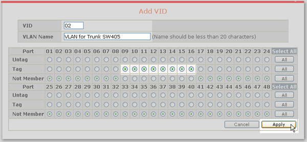
This example uses tagging for ports in VLAN 02. If you choose not to use tagging, remember that a port can be an untagged member of only one VLAN. If a port is already an untagged member of a VLAN, the switch will not let you select it as an untagged member of the new VLAN.
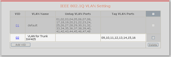
The new VLAN is shown on the VLAN Setting page:
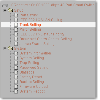
Now that the VLANs are in place, the trunk can be defined. In the menu, select Trunk Setting:
On the Trunking Configuration page, next to trunk ID 01, enter a Trunking Name, select 09,10,11,12 and click Apply as shown:
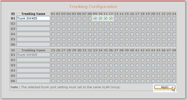
The first switch is now configured for trunking on ports 9–12 with ports 13–16 also able to use the trunk.
Repeat steps 1–5 to configure trunking on the second smart switch.
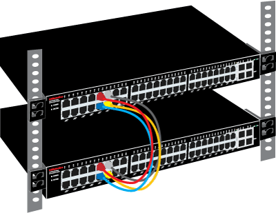
Connect the two switches on ports 9–12 using 4 ethernet cables:
