Contents:
Overview of the Web-based Management
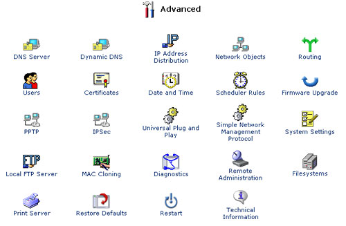
Advanced >
USR8200 Firewall/VPN/NAS User Guide
Advanced Features
This section of the Management Console is intended primarily for more advanced users. Some changes to settings within this section should be made with caution, as they could adversely affect the operation of the USR8200 Firewall/VPN/NAS and the home network. Click on one of these links to learn about the different functions on the advanced feature page:
- DNS Server
- Dynamic DNS
- IP Address Distribution
- Network Objects
- Routing
- Users
- Certificates
- Date and Time
- Scheduler Rules
- Firmware Upgrade
- PPTP
- IPSec
- Universal Plug and Play
- Simple Network Management Protocol
- System Settings
- Local FTP Server
- MAC Cloning
- Diagnostics
- Remote Administration
- Filesystems
- Print Server
- Restore Defaults
- Restart
- Technical Information
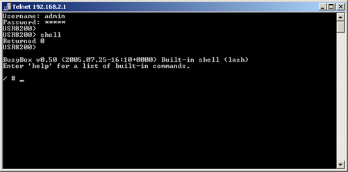
- Telnet
This is the Advanced page:

DNS (Domain Name System) Server
A DNS translates domain names into IP addresses and vice versa. The gateway's DNS server is an auto-learning DNS, which means that when a new computer is connected to the network, the DNS server learns its name and automatically adds it to the DNS table. Other network users may immediately communicate with this computer using either its name or its IP address. In addition, the gateway's DNS:
- Shares a common database of domain names and IP addresses with the DHCP server.
- Supports multiple subnets within the LAN simultaneously.
- Automatically appends a domain name to unqualified names.
- Allows new domain names to be added to the database.
- Permits a computer to have multiple host names.
- Permits a host name to have multiple IP addresses (needed if a host has multiple network cards).
- Does not require configuration. However, you may want to view the list of computers known by the DNS, edit the host name or IP address of a computer on the list, or manually add a new computer to the list.
View or Modify the DNS Table
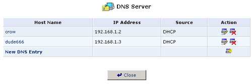
To view the list of computers stored in the DNS table, click the DNS Server icon in the Advanced screen of the Management Console. The DNS table will be displayed.
To add a new entry to the list:
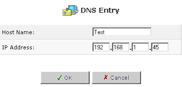
- Click New DNS Entry. The DNS Entry screen will appear.
- Enter the computer's host name and IP address.
- Click OK to save your changes.
To edit the host name or IP address of an entry:
- In the Action column of the DNS Server page, click the Edit button. The DNS Entry screen will appear. If the host was manually added to the DNS table, then you may modify its host name and/or IP address. Otherwise you may only modify its host name.
- Click OK to save your changes.
To remove a host from the DNS table, click the Remove button in the Action column. The entry will be removed from the table.
Dynamic DNS
The Dynamic DNS service allows you to alias a dynamic IP address to a static host name, allowing your computer to be more easily accessible from various locations on the Internet. Typically, when you connect to the Internet, your service provider assigns an unused IP address from a pool of IP addresses, and this address is used only for the duration of a specific connection. Dynamically assigning addresses extends the usable pool of available IP addresses, while maintaining a constant domain name. Each time the IP address provided by your ISP changes, the DNS database will change accordingly to reflect the change in IP address. In this way, even though a domain name's IP address will change often, your domain name will still be accessible.
To be able to use the Dynamic DNS feature you must open a DDNS account, free of charge, at http://www.DynDNS.org/account/create.html. When applying for an account, you need to specify a user name and password. Have them readily available when customising your DDNS support. For more information regarding Dynamic DNS, refer to http://www.DynDNS.org
Using Dynamic DNS
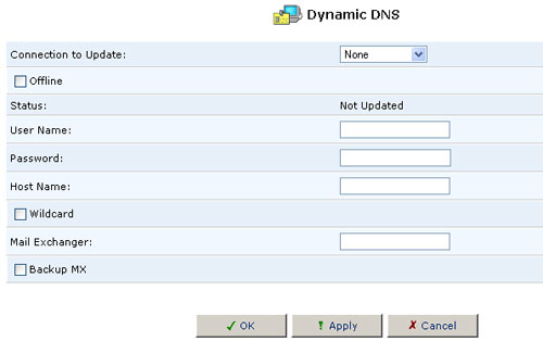
- Click the Dynamic DNS icon in the Advanced screen of the Management Console. The Dynamic DNS table will appear.
- Specify the Dynamic DNS operating parameters.
- User Name - Enter your DynDNS user name.
- Password - Enter your DynDNS password.
- Host Name - Enter a subdomain name and select a suffix from the domain list to define your host name.
- Mail Exchanger - Enter your mail exchange server address to redirect all e-mail messages arriving at your DynDNS address to the mail server.
- Select the Dynamic Update checkbox to enable the Dynamic DNS service.
IP Address Distribution
Your gateway's DHCP server lets you easily add computers that are configured as DHCP clients in the home network. It provides a mechanism for allocating IP addresses to these hosts and for delivering network configuration parameters to them.
Here's how it works: A client (host) sends out a broadcast message on the LAN requesting an IP address for itself. The DHCP server then checks its list of available addresses and "leases" a local IP address to the host for a specific period of time. It also simultaneously designates this IP address as "taken." The lease also contains other information about network services such as the gateway's netmask, route, and DNS server addresses. When the process is complete, the host is configured with an IP address for the duration of the lease.
When a lease nears expiration, the host can renew it or let it expire. If it renews the lease, then it will also receive current information about network services, as it did with the original lease. This allows it to update its network configuration to reflect any changes that have occurred since it first connected to the network. If the host wants to terminate a lease before its expiration, it can send a release message to the DHCP server, which then makes the IP address available for use by others.
The gateway's DHCP server:
- Displays a list of all DHCP hosts connected to the USR8200 Firewall/VPN/NAS
- Defines the range of IP addresses that can be allocated in the LAN
- Defines the length of time for which dynamic IP addresses are allocated (lease time)
- Can assign a static IP address (also called a static lease) to a LAN computer so it receives the same IP address each time it connects to the network, even if this IP address is within the range of addresses that the DHCP server may assign to other computers
- Provides the DNS server with the host name and IP address of each computer that is connected to the LAN
DHCP Server Summary
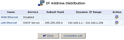
To view a summary of the services currently being provided by the DHCP server, click the DHCP icon in the Advanced screen of the Management Console. The DHCP Server Summary screen appears. Select Clear the Name check box to enable or disable DHCP services for a device.
Note: If a device is listed as "Disabled," it means that DHCP services are not being provided to hosts connected to the network through that device. The gateway will not assign IP addresses to these computers, which is useful if you want to work with static IP addresses only.
Editing DHCP Server Settings
To edit the DHCP server settings for a device:
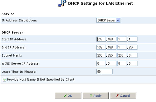
- Click the Edit button in the Action column. The DHCP Settings for this device appears.
- Choose whether to enable or disable the DHCP service for this device. You can also do this on the DHCP Server Summary screen.
- Complete the following fields and then click OK.
- IP Address Range (Start and End): This determines the number of hosts that may be connected to the network in this subnet. "Start" specifies the first IP address in the range that may be assigned in this subnet and "End" specifies the last IP address in the range.
- Subnet Mask: A mask used to determine which subnet an IP address belongs to. An example of a subnet mask value is 255.255.0.0.
- Lease Time: This the length of the machine's lease period (described above). When the lease expires, the server determines if the computer has disconnected from the network. If so, the server may reassign this IP address to the next newly-connected computer. This ensures that IP addresses that are not in use will become available for other computers on the network.
- Provide Host Name If Not Specified by Client: If the DHCP client does not have a host name, the gateway will assign the client a default name.
DHCP Connections
To view a list of computers currently recognized by the DHCP server, click the Connection List button that appears at the bottom of the DHCP Server Summary screen. The DHCP Connections screen will be displayed.
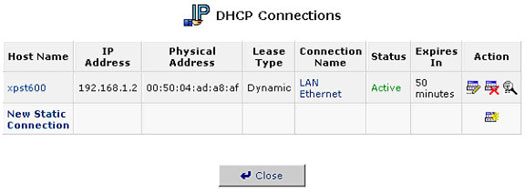
To edit the properties for a static connection:
Click the Action column's Edit button. The DHCP Connection Settings screen appears.

To define a new connection with a fixed IP address:
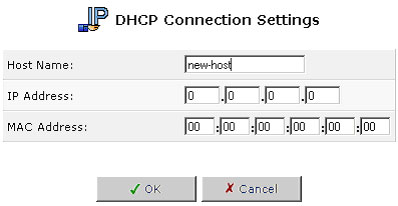
- Click the New Static Connection button that appears on top of the DHCP Connections screen. The DHCP Connection Settings screen appears.
- Enter a host name for this connection.
- Enter the fixed IP address that you would like to have assigned to the computer.
- Enter the MAC address of the computer's network card.
- Click OK to save your changes. To remove a host from the table, click the Delete button that appears in the Action column.
Note: A device's fixed IP address is actually assigned to the specific network interface card (NIC) installed on the LAN computer. If you ever replace the NIC, you must update the device's entry in the DHCP Connections list with the new network card's MAC address.
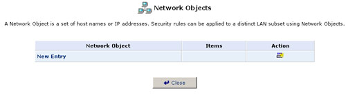
Network Objects
The Network Objects screen provides a method of abstractly defining a set of LAN hosts. You can then apply system rules to the group to implement filtering by IP address, host name, or MAC address.
To define a network object:
1. Click the Network Objects icon and the Network Objects screen will appear.
2. Click New Entry and the Network Objects screen will appear.
3. Specify a name for the network object in the Description field.
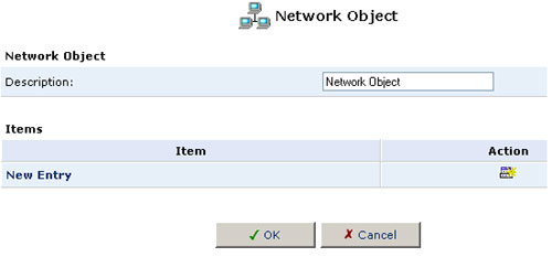
4. Click New Entry and the Item screen will appear.
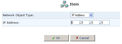
5. Select the type of network object type from the Network Object Type pull-down menu:
- IP Address
- MAC Address
- Host Name
6. Enter the appropriate description for the network object type and then click OK.
7. Click OK in the Network Object screen and then click Close.
Routing
Managing Routing Table Rules
You can access the routing table rules by clicking the Routing icon from the Advanced screen. The Routing screen will appear.
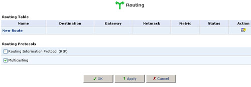
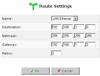
You can add, edit, and delete routing rules from the Routing Table. When adding a routing rule, you need to specify:
- Device: Select the network device.
- Destination: The destination is the destination host, subnet address, network address, or default route. The destination for a default route is 0.0.0.0.
- Netmask: The network mask is used in conjunction with the destination to determine when a route is used.
- Gateway: Enter the gateway's IP address.
- Metric: A measurement of the preference of a route. Typically, the lowest metric is the most preferred route. If multiple routes exist to a given destination network, the route with the lowest metric is used.
Multicasting
The USR8200 Firewall/VPN/NAS provides support for IGMP multicasting, which allows hosts connected to a network to be updated whenever an important change occurs in the network. A multicast is simply a message that is sent simultaneously to a predefined group of recipients. When you join a multicast group, you will receive all messages addressed to the group, much like what happens when an e-mail message is sent to a mailing list.
IGMP multicasting enables UPnP capabilities over wireless networks and may also be useful when connected to the Internet through a router. When an application running on a computer in the home network sends out a request to join a multicast group, the USR8200 Firewall/VPN/NAS intercepts and processes the request. If the USR8200 Firewall/VPN/NAS is set to Minimum Security, no further action is required. However, if the USR8200 Firewall/VPN/NAS is set to Typical Security or Maximum Security, you must add the group's IP address to the USR8200 Firewall/VPN/NAS's Multicast Groups screen. This will allow incoming messages addressed to the group to pass through the Firewall and on to the correct LAN computer.
- Click the Routing icon in the Advanced screen.
- Select the Multicast Groups Management check box.
- Click OK.
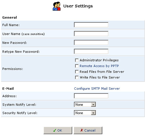
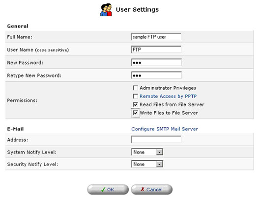
Users
User Settings
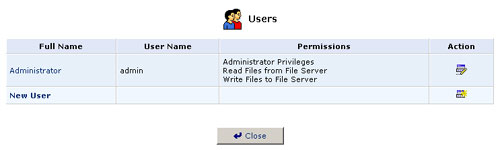
This is the section you will use to add new users for utilizing the PPTP, File Server, and FTP Server functions.
To create an account, click New User.
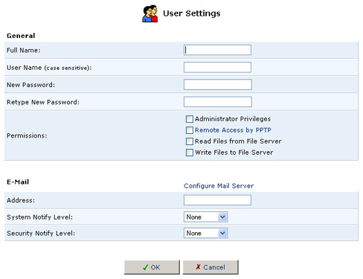
- Full Name: The user's full name.
- User Name: The name the user will use to access your home network.
- New Password: Type a new password for the user. If you do not want to change the user's password, leave this field empty.
- Retype New Password: If a new password was assigned, type it again to verify it.
- Permissions: Select the user's privileges on your home network.
- Administrative Privileges: This gives users Administrative access to change setting via the Web-based management and Telnet.
- Remote Access by PPTP: This gives users the ability to remotely connect to your internal network.
- Read Files from the File Server: This gives users the ability to read files from either FTP or the File Servers.
- Write Files to the File Server: This gives users the ability to write files from either FTP or the File Servers.
- E-Mail Address: Type in the e-mail address of the user.
- Choose the System Notify Level: None, Error, Warning, or Information
- Choose the Security Notify Level: None, Error, Warning, or Information
The Notification levels are used to e-mail users the System and Security Log files. The type of information you will receive depends on the Level you choose for either.
Finally click OK to save the New User to the USR8200 Firewall/VPN/NAS. Note: User Names and Passwords are case sensitive
Note: Windows 95/98 users for File Server and FTP Server access, the username and password needs to be in all lowercase, not UPPERCASE.
Certificates
When working with public-key cryptography, you should be careful and make sure that you are using the correct person's public key. Man-in-the-middle attacks pose a potential threat, where an ill-intending third-party posts a phony key with the name and user ID of an intended recipient. Data transfer that is intercepted by the owner of the counterfeit key can fall into the wrong hands.
Digital certificates provide a means for establishing whether a public key truly belongs to the supposed owner. It is a digital form of credential. It has information on it that identifies you and an authorised statement to the effect that someone else has confirmed your identity.
Digital certificates are used to foil attempts by an ill-intending party to use an unauthorised public key. A digital certificate consists of the following:
- A public key: Certificate information. The "identity" of the user, such as name, user ID, etc.
- Digital signatures: A statement that tells that the information enclosed in the certificate has been vouched for by a Certificate Authority (CA). Binding this information together, a certificate is a public key with identification forms attached, coupled with a stamp of approval by a trusted party.
X.509 Certificate
The USR8200 Firewall/VPN/NAS supports X.509 certificates that comply with the ITU-T X.509 international standard. An X.509 certificate is a collection of a standard set of fields containing information about a user or device and their corresponding public 8.10 key. The X.509 standard defines what information goes into the certificate and describes how to encode it (the data format). All X.509 certificates have the following data:
The certificate holder's public key - the public key of the certificate holder, together with an algorithm identifier that specifies which cryptosystem the key belongs to and any associated key parameters.
The serial number of the certificate - the entity (application or person) that created the certificate is responsible for assigning it a unique serial number to distinguish it from other certificates it issues. This information is used in numerous ways; for example when a certificate is revoked, its serial number is placed on a Certificate Revocation List (CRL).
The certificate holder's unique identifier (or DN-distinguished name) - this name is intended to be unique across the Internet. A DN consists of multiple subsections and may look something like this: CN=John Smith, EMAIL=johndoe@usr.com, OU=R&D, O=U.S. Robotics, C=US (These refer to the subject's common name, organizational unit, organization, and country.)
The certificate's validity period the certificate's start date/time and expiration date/time - indicates when the certificate will expire.
The unique name of the certificate issuer - the unique name of the entity that signed the certificate. This is normally a CA. Using the certificate implies trusting the entity that signed this certificate.
Note: In some cases, such as root or top-level CA certificates, the issuer signs its own certificate.
The digital signature of the issuer - the signature using the private key of the entity that issued the certificate.
The signature algorithm identifier - identifies the algorithm used by the CA to sign the certificate.
Obtaining an X509 Certificate
To obtain an X509 certificate, you must ask a CA to issue you one. You provide your public key, proof that you possess the corresponding private key, and some specific information about yourself. You then digitally sign the information and send the whole package - the certificate request - to the CA. The CA then performs some due diligence in verifying that the information you provided is correct and, if so, generates the certificate and returns it.
You might think of an X509 certificate as looking like a standard paper certificate with a public key taped to it. It has your name and some information about you on it, plus the signature of the person who issued it to you.

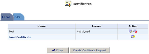
- Click the Certificates icon in the Advanced screen of the Management Console. The Certificates screen will appear.
- Click the USR8200 Firewall/VPN/NAS's Local Certificates button.
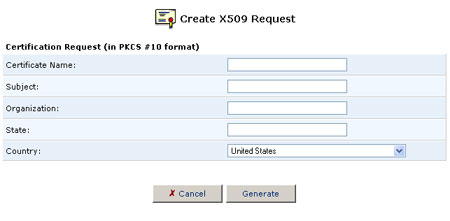
- Click the Create Certificate Request button. The Create X509 Request screen will appear.
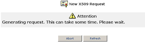
- Enter the following certification request parameters and click the Generate button. A screen will appear stating that the certification request is being generated.
- Certificate Name
- Subject
- Organization
- State
- Country
- After a short while, the screen will refresh and display your certification request.
- Store the exact contents of this request to a file, and send it to a CA for signing.
- Click Close. The main certificate management screen will appear, listing your certificate as "Not-signed."
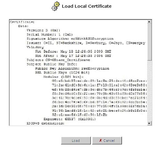
- After receiving a reply from the CA in the form of a signed request,
click Load Certificate. The Load Local Certificate screen will
appear.
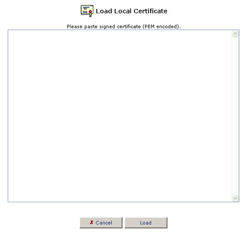
- Paste the signed request into the available space.
- Click the Load button to register the signed certificate. If the registration is successful, the certificate management screen will appear, displaying the certificate name and issuer.
Registering a CA's Certificate
- Click the Certificates icon in the Advanced screen of the Management Console. The Certificates screen will appear.
- Click the CA's Certificates button.
- Click the Load Certificate button. The Load CA's Certificate screen will appear.
- Paste the CA's certificate.
- Click the Load button.
Date & Time
Click the Date and Time icon in the Advanced screen of the Web-based Management to set the local date and time information for the USR8200 Firewall/VPN/NAS.
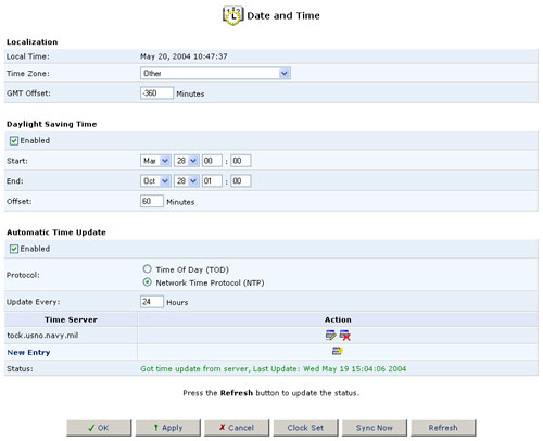
Localization:
Select the local time zone from the pull-down menu.
Daylight Saving Time:
Depending on which time zone you choose, you may or may not see the Daylight Saving Time option. The USR8200 Firewall/VPN/NAS can automatically adjust the local time that it stores internally when Daylight Savings Time (DST) begins and ends.
To do this select Enabled and then in the following fields enter the dates on which Daylight Savings Time begins and ends at your location.
Below is a chart for the years 2003 - 2005.
|
United States
|
||
|
Year
|
DST Begins at A.M.
|
DST Ends at A.M.
|
|
2003
|
April 6
|
October 26
|
|
2004
|
April 4
|
October 31
|
|
2005
|
April 3
|
October 30
|
|
European
|
||
|
Year
|
DST Begins at A.M.
|
DST Ends at A.M.
|
|
2003
|
March 30
|
October 26
|
|
2004
|
March 28
|
October 31
|
|
2005
|
March 27
|
October 30
|
For a very informative description of what Daylight Saving Time is and its history, along with a calculator, you can visit http://webexhibits.org/daylightsaving/index.html
For more information about this or any other feature, refer to the USR8200 Firewall/VPN/NAS Web Support page.
Automatic Time Update:
The USR8200 Firewall/VPN/NAS can keep the time always in sync with Universal time standards by connecting to Time servers throughout the world.
To do this select Enabled and then in the following fields enter the server address, the protocol used by the server, and how often you want the time to be updated.
Below are a few worldwide NTP Servers.United States:
US IL ntp0.mcs.anl.gov (140.221.8.88)
US NY nist1-ny.glassey.com (208.184.49.9)
US CA clepsydra.dec.com (204.123.2.5Europe:
FR canon.inria.fr (192.93.2.20)
DE ntp0.fau.de (131.188.3.220)You can find a complete listing of public servers from the following Web site: http://www.eecis.udel.edu/~mills/ntp/servers.html
If you click Clock Set, you will be able to assign the settings for the Local Date and Local Time.
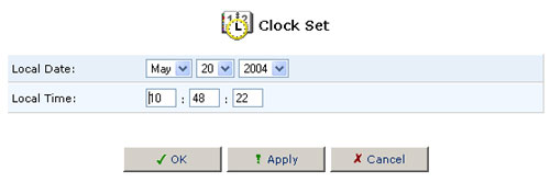
After you have set the date and time, click OK.
Scheduler Rules
Scheduler rules are used for limiting the application of Firewall rules to specific time periods, specified in days and hours.
To define a rule:
1. Click the Scheduler Rules icon and the Scheduler Rules screen will appear.
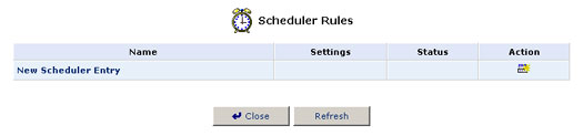
2. Click New Scheduler Entry and the Scheduler Rule Edit screen will appear.
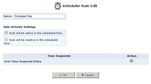
3. Specify a name for the rule in the Name field.
4. Specify if the rule will be active or inactive during the designated time period by selecting the appropriate Rule Activity Settings checkbox.
5. Click New Time Segment Entry to define the time segment that the rule will apply to. The Time Segment Edit screen will appear.
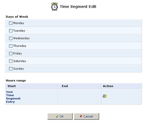
- Select active and/or inactive days of the week.
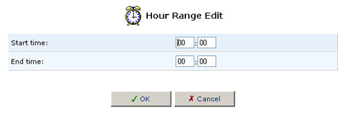
- Click New Time Segment Entry to define an active/inactive hourly
range and then click OK.
- Click OK.
6. Click OK and then click OK again to return to the Advanced
screen.
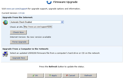
Firmware Upgrade
There are two ways to upgrade the system software:
- Upgrading from the Internet: automatically retrieve an updated system software file.
- Upgrading from a local computer: use an update system software file located on a local disk drive. The following are instructions for each of these methods.
Upgrading From the Internet
To learn if an upgrade is available, click the Firmware Upgrade button from the Advanced screen. Then click Check Now. You may need to click Refresh after a few seconds. You will be informed whether an upgrade is available. If so, click Force Upgrade if you wish to upgrade to the latest code for the USR8200 Firewall/VPN/NAS.
If an upgrade is available:
- To upgrade, click the Yes button.
- To wait and upgrade later, do one of the following:
A) Click the No button. The system will continue to perform its daily checks for the availability of a software update as scheduled and will notify you the next time you log into the Management Console.
Note: The Gateway must be connected to the Internet in order to communicate with the Remote Update server. Those systems that store the time internally will attempt to connect and check for an update weekly. The default upgrade path is http://www.usr.com/support/8200/8200-files/usr8200.rmt
B) Move to another screen by clicking an icon in the left sidebar. Return to the Upgrade screen at a later time by clicking the Firmware Upgrade icon in the Advanced screen.
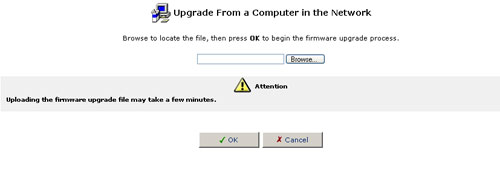
Upgrading From a Local Computer
To upgrade the USR8200 Firewall/VPN/NAS using a file that you have previously downloaded from the Internet or received on CD-ROM:
- When you receive notification that a new software version is available, retrieve the file as instructed and store it on a computer in the home network.
- Open the Management Console from this same computer and click the Firmware Upgrade icon in the Advanced screen In the Firmware Upgrade screen, click Upgrade Now.
- Click Browse. A dialog box will appear. Choose the file to upload to the USR8200 Firewall/VPN/NAS and click Open.
- Click OK at the bottom of the Upgrade screen. The file will be uploaded to the USR8200 Firewall/VPN/NAS.
- After the file has been transferred to the USR8200 Firewall/VPN/NAS, its validity will be verified and you will be asked to confirm that you want to upgrade the USR8200 Firewall/VPN/NAS with this new file.
- Click Yes to confirm. The upgrade process will begin and should take no longer than one minute to complete.
- At the conclusion of the upgrade process, the USR8200 Firewall/VPN/NAS will automatically reboot. The new software version of will be running, and your custom configurations and settings will be maintained.
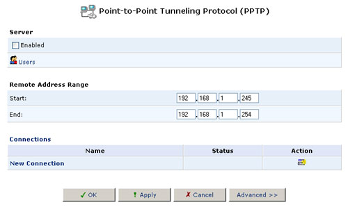
Point-to-Point Tunneling Protocol (PPTP)
There are two modes in which the USR8200 Firewall/VPN/NAS can use PPTP:
- Server mode, where the USR8200 allows remote users to log in to the local network, and
- Client mode, in which a local machine connects to a remote network over the Internet.
To access the PPTP settings, click the PPTP icon from the Advanced screen. The Advanced PPTP Settings screen will appear. This screen enables you to configure:
- The remote users that will be granted access to your home network.
- The IP address range an authorised remote user can use when accessing your home network.
- Advanced PPTP client/server connection settings.
Managing Remote Users
Click Users to define and manage remote users. You can add, edit, and delete users. When adding a user, you need to specify the following parameters:
- Full Name: The remote user's full name.
- User Name: The name a remote user will use to access your home network.
- New Password: Type a new password for the remote user. If you do not want to change the remote user's password, leave this field empty.
- Retype New Password: If a new password was assigned, type it again to verify it.
- Permissions: Select the remote user's privileges on your home
network.
- Administrative Privileges: This gives users Administrative access to change setting via the Web-based management and Telnet.
- Remote Access by PPTP: This gives users the ability to remotely connect to your internal network.
- Read Files from the File Server: This gives users the ability to read files from either FTP or the File Servers.
- Write Files to the File Server: This gives users the ability to write files from either FTP or the File Servers.
- E-Mail Address: The remote user's e-mail address.
- Choose the System Notify Level: None, Error, Warning, or Information
- Choose the Security Notify Level: None, Error, Warning, or Information
The notification levels are used to e-mail users the System and Security Log files. The type of information you will receive depends on the Level you choose for either.
Note: Changing the settings for any active user connection (i.e., where the user is currently connected) terminates that user's session. For changes to take effect, you should activate the connection manually after modifying the user parameters.
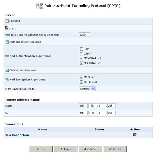
Advanced PPTP Server Settings
In server mode, the USR8200 Firewall/VPN/NAS enables remote users to access your local network. To configure advanced PPTP server settings, click the Advanced button on the PPTP screen. The Advanced PPTP Settings screen will appear. This screen enables you to configure the following:
- Enabled: Use this checkbox to enable or disable the PPTP server.
- Maximum Idle Time to Disconnect: Specify the amount of idle time (during which no data is sent or received) that should elapse before the gateway disconnects a PPTP connection.
- Authentication Required: Enable or disable the authentication option.
- Allowed Authentication Algorithms: Select the algorithms the server may use when authenticating its clients.
- Encryption Required: Enable or disable the encryption option.
- Allowed Encryption Algorithms: Select the algorithms the server may use when encrypting data.
- Remote Address Range: Specify the range of IP addresses remote users can use to access your home network. Note that the server settings you choose here must be the same as the corresponding client settings (on the machines that will access your local network). The USR8200 Firewall/VPN/NAS has its own DHCP server to allocate its available IP addresses to remote clients.
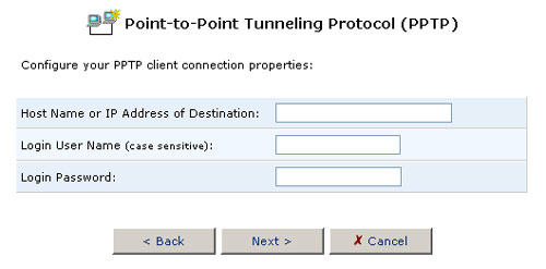
Creating a New Connection
To create a new PPTP connection, click New Connection at the bottom of the main PPTP screen. The new connection properties screen will be displayed. Enter the following information:
- Host Name or Destination IP Address
- Login User Name
- Login Password
When you have entered this information, click Next.
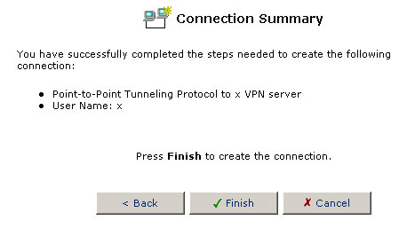
On the next screen, verify the information you entered and click Finish if it is correct. If it is not correct, click Back and re-renter the information.
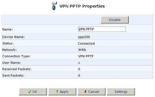
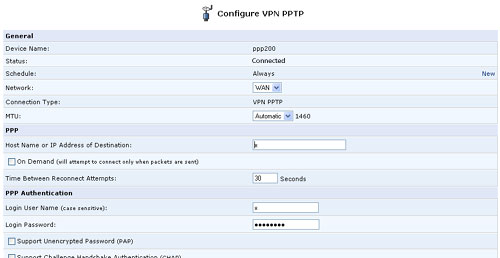
Advanced PPTP Client Settings
In client mode, the USR8200 Firewall/VPN/NAS helps local users access a remote network.The PPTP connections are displayed in the Advanced PPTP Settings screen.
All settings entered here must be the same as those entered in the remote PPTP server. If they do not match and you cannot change them in the client, you can switch to the PPTP client built into the operating system and configure it as you need.
To configure advanced PPTP client and server settings, perform the following steps:
- Click the connection's Edit button. The Connection Summary screen will appear.
- Click the Settings button. The Advanced PPTP Client Settings screen will appear, enabling you to configure the following advanced PPTP client settings.
- Device Name: This is a connection name chosen by the USR8200 Firewall/VPN/NAS.
- Status: This shows the current PPTP state.
- Schedule: A schedule defines when the tunnel is available. You can define a scheduler rule that lists days of the week and hours of the day when the tunnel is enabled. Click here for more information on this.
- Network: This indicates where the tunnel's other endpoint is. Use WAN if the USR8200 Firewall/VPN/NAS will communicate with its peer machine over the Internet.
- Connection Type: This is the type of PPTP connection you are configuring.
- MTU: The Maximum Transmission Unit (MTU) is the largest physical packet size, measured in bytes that will be transmitted through the PPTP connection. Packets larger than the MTU are divided into smaller packets before being sent. You can set the MTU size manually, or select an automatic MTU mode.
- Host Name or IP Address of Destination: This tells the USR8200 Firewall/VPN/NAS where the endpoint of the PPTP connection is.
- On Demand: If you enable this check box, the USR8200 only tries to connect to its peer machine when there is data to transmit. If you disable this, the USR8200 makes the connection when it starts up.
- Time Before Reconnect Attempts: This is how long the USR8200 Firewall/VPN/NAS waits after losing its connection to the peer before it tries to re-establish the connection.
- Login User Name: This is the user name for logging in to the peer machine.
- Login Password: The password for logging in to the peer machine.
- Support Unencrypted Password (PAP): Enable this item if you want the login to the peer machine to include sending a non-encrypted password.
- Support Challenge Handshake Authentication (CHAP): Enable this check box if you want the login to the peer machine to include sending an encrypted password. CHAP is much more secure than the PAP method.
- Support Microsoft CHAP: This is a more recent (and more secure) version of CHAP.
- Support Microsoft CHAP Version 2: This is the most recent (and most secure) version of CHAP.
- Require Encryption: Set this item if you want the USR8200 Firewall/VPN/NAS and its peer to use PPP encryption in messages sent to each other. If this box is checked, a connection is not set up if the peer machine declines encryption.
- Support Encryption: Check this box if you want the USR8200 Firewall/VPN/NAS to encrypt messages sent to the peer with standard-size encryption keys.
- Support Maximum Strength Encryption: Check this box if you want to use encryption with larger keys for added security.
- Internet Protocol: This item affects how the local machine gets its IP address to use the tunnel. Select Use the Following IP Address and enter the address below if the remote system administrator gave you a specific IP address to use. If not, choose Obtain an IP Address Automatically and the machine will use its normal IP address.
- Override Subnet Mask: You can use this mask to specify the subnets your local machines wish to access on the remote network.
- DNS Server: Select whether the PPTP client should obtain a domain name service (DNS) address automatically. If not, you need to enter primary and secondary IP addresses for DNS servers.
- Routing: This setting lets you define the routing rules for the PPTP client's connections. If you select Advanced, With Advanced, you can set up the routing mode and the maximum number of hops to reach the peer machine in (this is called Device Metric; we suggest that only experienced network administrators change it). You can also enable or disable the default route to the tunnel, enable broadcast messages, and have the USR8200 listen for RIP (Routing Information Protocol) data.
- Internet Connection Firewall: Select this check box to include the PPTP client connection as a network interface monitored by the USR8200's firewall. Click on the words Internet Connection Firewall to go to the main firewall configation page.
Internet Protocol Security (IPSec)
To access the Advanced IPSec Settings, click the IPSec icon in the Advanced screen. The IPSec Connections screen will appear. This screen displays your IPSec connections and enables you to configure the following:
- General IPSec settings
- Key management
- Log settings - Advanced IPSec connection settings
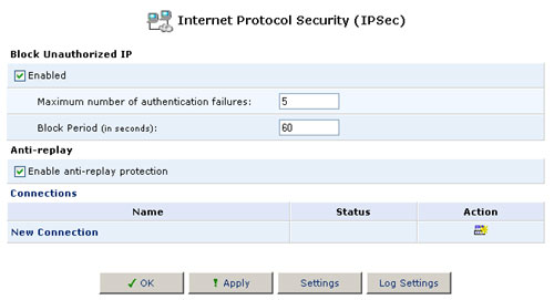
General IPSec Settings
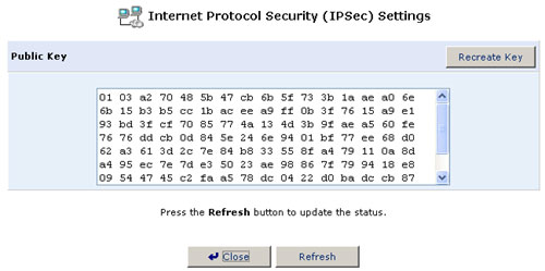
Key Management
- Click Settings. The Key Management screen will appear.
- The Key Management screen displays the public key of the USR8200 Firewall/VPN/NAS. If necessary, you can copy the public key from this screen.
- Click Recreate Key to recreate the public key or click Refresh
to refresh the key displayed in this screen.
Log Settings
The IPSec log can be used to identify and analyze the history of the IPSec package commands, attempts to create connections, etc. IPSec activity, as well as that of other USR8200 Firewall/VPN/NAS modules, is displayed together in this view.
- Click the IPSec icon in the Advanced screen.
- Click Log Settings. The IPSec Log Settings screen will appear.
- Select the checkboxes relevant to the information you would like the
IPSec log to record.
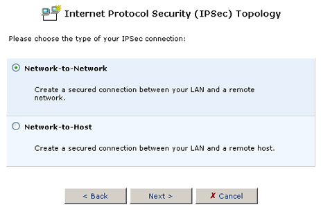
Setting up IPSec
Follow this procedure to configure an IPSec connection:
- Starting at the IPSec configuration page, click on New Connection (just above the OK button).
- To set up a connection from the USR8200 Firewall/VPN/NAS to a peer network rather than to a single machine, select Network-to-Network and click OK. Otherwise, select Network-to-Host and click OK.
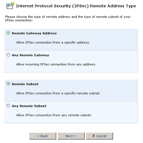
- In the following page, choose whether you want to make the IPSec connection with a specific host or any host, and with a specific subnet or any subnet.
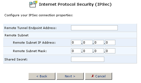
- In the next page, you can enter a shared secret (described below) and information on the remote peer (depending on what you selected in the previous step):
- (Skip this step if you selected Any Remote Gateway above.) Enter the URL for the tunnel's endpoint.
- (Skip this step if you selected Any Remote Subnet above.) Enter an IP address and mask for the remote subnet.
- Enter a shared secret, which is simply a text string that only the USR8200 Firewall/VPN/NAS and its IPSec peer know. For improved security, we suggest that you pick a string that will be difficult for attackers to guess. The same text string must also be entered in the peer's IPSec configuration.
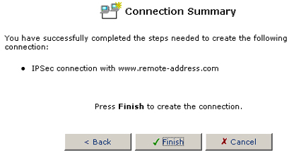
- When the following page appears, click Finish to save the IPSec connection:
Advanced IPSec Connection Settings
All settings entered here must be the same as those entered in the IPSec peer. If they do not match and you cannot change them on your end, you can switch to the IPSec client built into the operating system and configure it as you need.
The IPSec connections are displayed in the IPSec Connections screen. To configure advanced IPSec settings, perform the following steps:
- Click Edit for the connection. The Connection Summary screen will appear.
- Click Settings. The Advanced IPSec Settings screen will appear,
allowing you to configure the following advanced IPSec settings:
Device Name: This is a name assigned by the USR8200 Firewall/VPN/NAS for the IPSec peer -- the machine at the other endpoint of the tunnel.
Status: Connected means that the tunnel is up. Waiting for Connection means that the USR8200 Firewall/VPN/NAS is ready to accept a VPN connection from the peer system. Inactive says that the tunnel exists but is not being used by either side. Resolving Hostname appears when the USR8200 Firewall/VPN/NAS is trying to find a transmission route to the peer.
Schedule: A schedule defines when the tunnel is available. You can define a scheduler rule that lists days of the week and hours of the day when the tunnel is enabled. Click here for more information on this.
Network: This indicates where the tunnel's other endpoint is. Use WAN if the USR8200 Firewall/VPN/NAS will communicate with the peer over the Internet.
Remote Tunnel Endpoint Address: This is the location of the IPSec peer. The tunnel will not work unless the USR8200 and the machine specified here are the systems trying to use it. Any Remote Gateway means that the tunnel can accept a connection request from any device that wants to try to connect (though it's virtually impossible that the tunnel will work unless the peer has the correct shared secret, RSA signature, or certificate).
Security Association Mode: This can be either Tunneling or Transport. In Tunneling, the entire IP datagram is protected, while in Transport mode only the data for the higher-level protocols is protected. Transport mode needs no explicit configuration. Tunneling requires that you configure the local and remote subnet addresses and masks (described below). Use transport mode when the cryptographic endpoint is the same as the communication endpoint -- in other words, if the final message recipient is also the machine that decrypts the data.
Local Subnet: Here you tell the USR8200 Firewall/VPN/NAS which system or systems will use the tunnel at your (local) end -- a subnet, a range of IP addresses, or a single machine. If you specify multiple machines, any of them can use the tunnel, though only one can use it at a time. Below Local Subnet, you can enter the IP address(es) and/or the subnet mask.
Remote Subnet: This specifies which system or systems will use the tunnel at the peer end -- a subnet, a range of IP addresses, or a single machine. If you specify multiple machines, any of them can use the tunnel, though only one can use it at a time. Below Remote Subnet, you can enter the IP address(es) and/or the subnet mask.
Compress (Support IPCOMP): Select this check box to use the IP Comp data compression protocol.
Route NetBIOS Broadcasts: You can enable this item if you want to look up other computers by their names rather than by x.x.x.x IP addresses. This convenience is offset by how the USR8200 Firewall/VPN/NAS will send messages to the peer even when the tunnel is not in use.
Key Exchange Method: To communicate securely over the Internet, the two ends of the tunnel must exchange encryption keys. This item specifies whether the key exchange is automatic or manual. Automatic is recommended unless the peer system does not support automated key exchange.
Auto Reconnect: If you enable this item, the USR8200 Firewall/VPN/NAS will automatically attempt to re-connect to the peer if it loses the connection.
The following are the parameters that are required to configure an Automatic key exchange (see below for the Manual key exchange settings):
Mode: Your choices here are Main Mode and Aggressive Mode. Aggressive mode is quicker but less flexible than main mode. However, in aggressive mode, the USR8200 Firewall/VPN/NAS sends its IPSec peer useful information that it doesn't send in main mode.
Negotiation attempts: Select the number of negotiation attempts to perform in Phase 1 of the automatic key exchange. If one of the peers is unable to authenticate the other in this many connection attempts, the tunnel will not be opened. If this item says Infinite, the USR8200 Firewall/VPN/NAS will attempt to negotiate a connection indefinitely.
Life Time in Seconds: The length of time before a security association automatically performs a renegotiatation. A short Life Time improves security by forcing the VPN hosts to update the encryption and authentication keys. However, every time the VPN tunnel renegotiates, users accessing remote resources are disconnected. Therefore, the default Life Time is recommended.
Rekey Margin: Specifies how long before a connection expires that attempts to negotiate a replacement should begin. It is similar to that of the Key Life Time and is given as an integer denoting seconds.
Rekey Fuzz Percent: Specifies the maximum percentage by which Rekey Margin should be randomly increased to randomize re-keying intervals.
Peer Authentication: Select the method by which the USR8200 Firewall/VPN/NAS will authenticate your IPSec peer:
- Shared Secret -- a shared secret is simply a text string. You enter the same string here and in the peer's IPSec setup. The machines authenticate each other by performing complex processing on the string. If the calculated result is the same as that sent by the other machine, it authenticates the other machine.
- RSA Signature -- RSA is a popular encryption method that uses complex mathematical operations involving large prime numbers. It is an asymmetric system -- the message is encoded and later decoded with two separate keys.
- Certificate -- with certificates, digitally signed identity statements are created by certifying agencies or individuals vouching for others. This is the most secure peer authentication method.
Encryption Algorithm: Select one or more encryption methods to use in the phase 1 of the negotiation. If the algorithms you check don't exactly match the ones specified by the IPSec peer, the tunnel does not open. DES-CBC is an early algorithm that has been cracked. 3DES-CBC uses three different encryption operations, each with 56-bit keys. The Advanced Encryption Standard (AES) is a collection of algorithms using 128-bit, 192-bit, or 256-bit keys.
Hash Algorithm: Select the hash algorithms that the USR8200 Firewall/VPN/NAS will attempt to use when negotiating with the IPSec peer.
Group Description Attribute: Here you can select which algorithm group to use for Diffie-Hellman key exchanges in phase 1. Group 5 is more secure than group 2, which in turn is more secure than group 1.
Life Time in Seconds: The length of time before a security association automatically performs a renegotiatation. A short Life Time improves security by forcing the VPN hosts to update the encryption and authentication keys. However, every time the VPN tunnel renegotiates, users accessing remote resources are disconnected. Therefore, the default Life Time is recommended.
Use Perfect Forward Secrecy (PFS): Select whether Perfect Forward Secrecy of keys is desired on the connections keying channel. With PFS, penetration of the key-exchange protocol does not compromise keys negotiated earlier.
Group Description Attribute: Here you can select which algorithm group to use for Diffie-Hellman key exchanges in phase 2. Group 5 is more secure than group 2, which in turn is more secure than group 1.
Encryption Algorithm: Select one or more encryption methods to use in the phase 2 of the negotiation. If the algorithms you check don't exactly match the phase 2 methods specified by the IPSec peer, the tunnel does not open. If you do not want encryption for phase 2, select either Allow AH Protocol or Allow ESP Protocol with Null-Encryption, depending on whether you're using IPSec's AH or ESP protocols.
Authentication Algorithm (for ESP Protocol): Select the encryption and authentication algorithms the USR8200 Firewall/VPN/NAS will use during Phase 2 of the automatic key exchange. You can choose 3DES-CBC, DES-CBC, or NULL encryption algorithms. Or you can choose MD5 or SHA1 authentication algorithms.
Hash Algorithm (for AH Protocol): Select the hash algorithms that the USR8200 Firewall/VPN/NAS will use during phase 2 of the automatic key exchange. You can choose the MD5 or SHA1 algorithms.
Routing: You can choose to use basic routing functions or more advanced routing. With Advanced, you can set up the maximum number of hops to reach the peer machine in (this is called Device Metric; we suggest that only experienced network administrators change this). You can also change the default route to the tunnel, enable broadcast messages, and have the USR8200 Firewall/VPN/NAS listen for RIP (Routing Information Protocol) data.
Internet Connection Firewall: Select this check box to include the IPSec connection as a network interface monitored by the USR8200 Firewall/VPN/NAS's firewall.
The following are the parameters that are required to configure a Manual key exchange (Automatic key exchange settings appear above):
Security Parameter Index (SPI): A 32-bit value that, together with IP address and security protocol, uniquely identifies a particular security association (SA). This value must be the same for both the local and remote tunnels.
Use Different Encryption Keys: Uncheck this box if you want the USR8200 Firewall/VPN/NAS and its peer to use the same keys. If you check the box, the local key must be identical to the peer's remote key, and the remote key must be the same as the peer's local key.
IPSec Protocol: Select the encryption and authentication algorithms. The choices are ESP and AH. ESP uses encryption, while AH does not.
Encryption Algorithm & Keys: All key values should be entered in hexadecimal (base 16) format.
Authentication Algorithm & Key: The algorithm choices are SHA1 & MD5. All key values should be entered in hexadecimal (base 16) format.
Routing: Define the connection's routing rules. Choices are Basic and Advanced.
Internet Connection Firewall: Select this check box to include the IPSec connection as a network interface monitored by the USR8200 Firewall/VPN/NAS's firewall.
VPNC Scenario Connection Instructions
This section describes how to use
the USR8200 Firewall/VPN/NAS to configure an IPSec gateway-to-gateway connection
with a pre-shared secret scenario developed by the VPN Consortium.
Network Configuration
An IPSec tunnel is established between Gateways A and B, serving as a
transparent and secure network for clients from subnets A and B. Because
the configuration of the Gateways is the same except for their IP addresses,
this section describes only the configuration of Gateway A. Configuration
of Gateway B is identical, where A and B are replaced by B and A respectively.
LAN Interface Settings
- Click the Network Connections icon on the sidebar and the Network Connections screen will appear.
- Click LAN Ethernet to access the LAN Ethernet properties screen.
- Click Settings and the LAN settings page will appear. Configure the following parameters:
- Internet Protocol: Select Use the Following IP Address.
- IP Address: Specify 10.5.6.1
- Subnet Mask: Specify 255.255.255.0
- IP Address Distribution: Select DHCP Server.
- Start IP Address: Specify 10.5.6.1
- End IP Address: Specify10.5.6.254
- Subnet Mask: Specify 255.255.255.0
- Click OK.
WAN Interface Settings
1. Click the Network Connections icon on the sidebar and the Network Connections screen will appear.
2. Click WAN Ethernet to access the WAN Ethernet properties screen.
3. Click Settings and the WAN settings page will appear. Configure the following parameters:
- Internet Protocol: Select Use the Following IP Address.
- IP Address: Specify 14.15.16.17
- Subnet Mask: Specify the appropriate subnet mask.
- Default Gateway: Specify the appropriate Default Gateway in order to enable IP routing.
4. Click OK.
Example: Gateway-to-Gateway VPN with Preshared Secrets
The following is an example gateway-to-gateway VPN setup that uses a preshared secret for authentication. In this example, Gateway A connects the internal LAN 10.5.6.0/24 to the Internet. Gateway A's LAN interface has the address 10.5.6.1, and its WAN (Internet) interface has the address 14.15.16.17.
Gateway B connects the internal LAN 172.23.9.0/24 to the Internet. Gateway B's WAN (Internet) interface has the address 22.23.24.25.
The IKE Phase 1 parameters used are:
- Main mode
- 3DES (Triple DES)
- SHA-1
- MODP group 2 (1024 bits)
- Preshared secret of hr5xb84l6aa9r6
- SA lifetime of 28800 seconds (eight hours) with no Kbytes re-keying
The IKE Phase 2 parameters used are:
- 3DES (Triple DES)
- SHA-1
- ESP tunnel mode
- MODP group 2 (1024 bits)
- Perfect forward secrecy for re-keying
- SA lifetime of 3600 seconds (one hour) with no Kbytes re-keying
- Selectors for all IP protocols, all ports, between 10.5.6.0/24 and 172.23.9.0/24, using IPv4 subnets
To set up Gateway A for this scenario, use the following steps:
- Click the Network Connections icon on the sidebar and the Network Connections screen will appear.
- Click New Connection and the wizard screen will appear. Select Internet Protocol Security (IPSec). Click Next. The IPSec Topology screen will appear.
- Select Network-to-Network to create a secure connection between your LAN and a remote network. Click Next. The Remote Address Type screen will appear.
- Select Remote Gateway Address to allow an IPSec connection from a specific address. Select Remote Subnet to allow an IPSec connection from a specific remote subnet. Click Next. The Connection Parameters screen will appear.
- Specify the following parameters:
- Remote Tunnel Endpoint Address: Specify 22.23.24.25
- Remote Subnet IP Address: Specify 172.23.9.0
- Remote Subnet Mask: Specify 255.255.255.0
- Shared Secret: Specify hr5xb84l6aa9r6
- Click Next. The Connection Summary screen will appear. Click Finish. The Network Connections screen will now list the newly created IPSec connection.
- Click Edit. The Connection Properties screen will appear. Click Settings. The IPSec Configuration screen will appear.
- Deselect the Compress checkbox.
- Deselect the Allow Peers to Use MD5 checkbox (located under Hash Algorithm).
- Deselect the DH Group 5 (1536 bit) checkbox (located under Group Description Attribute).
- Deselect the Allow AH Protocol (No Encryption) checkbox (located under Encryption Algorithm).
- Click OK. The Connection Properties screen will appear.
- Click OK. The Network Connections screen will appear. Note that the IPSec connections status has changed to Connected.
- Click Home on the sidebar to view the Network Map depiction
of the IPSec connection.
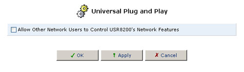
Universal Plug and Play (UPnP)
Select the checkbox to allow other users on the network to control the network features.
Simple Network Management Protocol (SNMP)
SNMP is a protocol that gathers information on network performance. It helps network administrators find problems and plan for future needs. In an SNMP-managed network, one computer acts as a network management system (NMS). The NMS runs an SNMP application that gathers and displays statistical data about what's happening on the network, storing the data in a management information base (MIB). The USR8200 Firewall/VPN/NAS and other network devices send data to the NMS when it asks. The USR8200 software calls the NMS the trusted peer.
To open the SNMP screen, click on SNMP from the advanced options page.
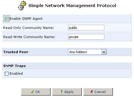
These are the fields on this screen:
| Item | Description |
| Enable SNMP Agent | Enable this to have the USR8200 Firewall/VPN/NAS respond to SNMP data collection requests. |
| Read-Only Community Name | A community is a collection of SNMP agents and network management systems. This item identifies what community the USR8200 Firewall/VPN/NAS has read-only access to. The USR8200 Firewall/VPN/NAS can read all of the data in a MIB but not write to it. |
| Read-Write Community Name | This identifies what community the USR8200 Firewall/VPN/NAS has read-write access to. The system can view and change all MIB data for this community. |
| Trusted Peer | This is the IP address of the network management system (NMS), which collects network performance information. |
| SNMP Traps | An SNMP trap is a notification that a specific event (such as a system restart) has occurred on the network. This checkbox enables or disables the generation of SNMP traps by the USR8200 Firewall/VPN/NAS whenever the NMS wants to monitor trap events. |
System Settings
In this area, you can view and modify the System, File Server, Management Console, Remote Administration, Management Application Ports, System Logging, Security Logging, and Outgoing Mail Server information.
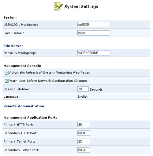
System
Hostname:
Used to set the Hostname by which other computers will see the USR8200 Firewall/VPN/NAS in Network Neighborhood, SMB, etc.Local Domain:
Used to set the Local Domain. This should be the same as the NetBIOS Workgroup under File Server.
File Server
NetBIOS Workgroup:
Used to set the Workgroup in which the USR8200 Firewall/VPN/NAS will reside in the Network. This should be the same as the Local Domain under System.
Management Console
Automatic Refresh of System Monitoring Web Pages
By default this is not enabled.Note: If this is enabled when viewing System Monitoring, System Logs, and Security Logs, your unit will be open to security risk if you walk away without exiting those screens.
Warn User Before Network Configuration Changes
If this is enabled, you will receive a notification if any changes are made to the configuration of the network. By default, this is enabled.Session Lifetime:
This is the inactivity time the USR8200 Firewall/VPN/NAS will wait before asking a user to re-log into the Web-based Management and Telnet. The maximum amount of time that can be entered is 1200 seconds.
Remote Administration
Refer to the Remote Administration section in this User Guide for information about this area.
Management Application Ports
You can modify the following fields:
- Primary HTTP Port
- Secondary HTTP Port
- Primary HTTPS Port
- Secondary HTTPS Port
- Primary Telnet Port
- Secondary Telnet Port
- Secure Telnet over SSL Port
System Logging
You can change the System Log Buffer Size in Kb. It is recommended that you leave the Buffer at the default size. You can also select the Remote System Notify Level from one of the following:
- None
- Error
- Warning
- Information
Security Logging
You can change the Security Log Buffer Size in Kb. It is recommended that you leave the Buffer at the default size. You can also select the Remote Security Notify Level from one of the following:
- None
- Error
- Warning
- Information
Outgoing Mail Server
This is for the outgoing mail server that the USR8200 Firewall/VPN/NAS will use to send out notifications for individual users that have Logging turned on for their account. You will need to enter the Server, the From Email Address, and the Port. You can also select or deselect Server Requires Authentication. If you select Server requires Authentication, you will need to enter the User Name and the Password for the Email account.
Local FTP Server
This section will allow you to enable, set allowed connections, grant anonymous read/write access, and put in the path to the folder for anonymous users.
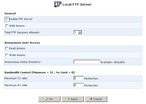
General
Enable FTP Server:
This will enable the FTP Server. Users are configured in the Users Settings section of the Advanced Menu.
Currently, a user added this way will have access to read or write to all hard disks installed onto the USR8200 Firewall/VPN/NAS.
WAN Access: This will enable a non-local client to make FTP file transfers to and from the USR8200 Firewall/VPN/NAS.
Total FTP Sessions Allowed: This will allow you to choose how many concurrent FTP connections are allowed at a time.
Anonymous User Access
Read Access: This will allow an anonymous user to read files located in the path you provide in the Anonymous Home Directory.
Write Access: This will allow an anonymous user to write/modify files located in the path you provide in the Anonymous Home Directory.
Anonymous Home Directory: This is where you must fill in a path for anonymous users to access a specific folder on a selected Hard Disk partition.
Example paths (drive names are case sensitive): /A/pub, /A/public, or /A/public access
Bandwidth Control
Maximum Tx rate: If you want to limit the FTP data transmission rate, enter the limit here. Enter 0 if you do not want to limit the transmission rate.
Maximum Rx rate: If you want to limit the FTP data receipt rate, enter the limit here. Enter 0 if you do not want to limit the receipt rate.
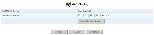
MAC Cloning
A MAC address is the numeric code that identifies a device on a network, such as your external cable/DSL modem or a computer network card. Your service provider may ask you to supply the MAC address of your computer, external modem, or both.
When replacing an external modem with the USR8200 Firewall/VPN/NAS, you can simplify the installation process by copying the MAC address of your existing computer to the USR8200 Firewall/VPN/NAS. In such a case, you do not need to delay the setup process by informing your ISP of newly installed equipment.
Using MAC Cloning
- Click the MAC Cloning icon in the Advanced screen of the Management Console. The MAC Cloning screen will appear.
- Enter the physical MAC address to be cloned.
- Click the Clone My MAC Address button.
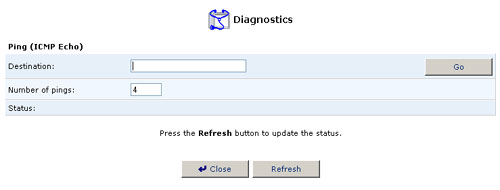
Diagnostics
The Diagnostics screen can assist you in testing network connectivity. This feature will enable you to ping (ICMP echo) an IP address and view statistics such as the number of packets transmitted and received, round trip time, and success status.
Diagnosing Network Connectivity
To diagnose network connectivity, perform the following steps:
- Click the Diagnostics icon from the Advanced screen in the management console. The Diagnostics screen will appear.
- Enter the IP address to be tested in the Destination field.
- Click Go.
- In a few seconds, diagnostics statistics will be displayed. If no
new information is displayed, click Refresh.
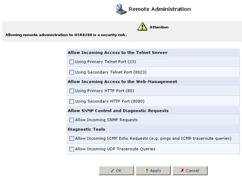
Remote Administration
In its default state, the USR8200 Firewall/VPN/NAS blocks all external users from connecting to or communicating with your network. Therefore, the system is safe from hackers who may try to intrude on the network and damage it. However, you may want to enable certain services that grant remote users administrative privileges in your network.
Configuring Remote Administration Services
- Click the Remote Administration icon in the Advanced screen
of the Management Console. The Remote Administration screen will appear.
- Select the check boxes next to the service names that you want to enable and then click OK.
Filesystems
The USR8200 Firewall/VPN/NAS can operate as a file server for storage devices that are connected via USB or FireWire. Your home network's LAN devices can share the storage device as a mapped network drive. The Web-based Management provides disk management utilities such as fdisk for partitioning the drive as a physical disk or logical disk, as well as format utilities for formatting the partitions.
The USR8200 Firewall/VPN/NAS supports up to 30 hard disks or 100 separate partitions, whichever comes first. The hard disks can be either daisy chained through FireWire hubs, USB 1.1/2.0 hubs, or a combination of both.
Note: Any hard disk connected through a USB 1.1 hub will not be running at full speed. The performance speed will be lowered as you add more hard disks through a USB 1.1 hub.
Note: For storage devices that come
with both a USB 1.1/2.0 connection and a FireWire connection, only one
port of the storage device can be used at a time.
When a hard disk or storage device is connected to the USR8200 Firewall/VPN/NAS via USB1.1/2.0 or FireWire, it will register on the network map. Viewing the network map as a list will display information about each storage device that is connected.
Note: Before disconnecting any hard
disk, it is recommended to unmount the hard disks using the web-based
management.
Each hard disk can have up to 16 partitions with an Extended partition and can have a maximum of four main partitions. Main partitions include primary and extended partitions. The following are some different partition configurations you can have in your hard disk.
- You can have up to three primary partitions and one extended partition
or up to four primary partitions. If you have four primary partitions
for the main partitions, the hard disk is limited to a total of four
partitions.
- If you have three primary partitions and one extended partition, you can add 12 more partitions through the logical partition within the extended partition.
The File Systems that are supported by the USR8200 Firewall/VPN/NAS for formatting a hard disk(s) partitions are Linux (ext2) and Windows (FAT32).
The File Systems that the USR8200 Firewall/VPN/NAS supports in Read/Write form are Linux (ext2), Windows (FAT12), Windows (FAT16), and Windows (FAT32).
If you are not sure if the hard disk you have connected to the USR8200 Firewall/VPN/NAS is pre-formatted, look in the network map. If the hard disk is pre-formatted, below the hard disk name you will see \\usr8200\A, \\usr8200\B, \\usr8200\C, etc.
If the hard disk you are adding to the USR8200 Firewall/VPN/NAS is pre-formatted and you do not wish to create or modify any partitions, proceed to the Setting up User access rights to the storage devices section in this chapter.
If the hard disk is not pre-formatted, or you are unsure, please proceed to the Managing Partitions section in this chapter.
Note: It is recommended to format the hard disk using EXT2 if you will be transferring large files to the hard disk. If you will not be transferring any files over 4 gigabytes, it is recommended to format the hard disk using FAT32.
Managing Partitions
The following buttons are the different Action icons in the File Management screens. These will appear in the Action column for each hard disk and partition associated with the USR8200 Firewall/VPN/NAS. Only the icons for the actions that can be performed on a hard disk or partition will appear. For example, the Delete a partition icon will not appear if there are no partitions on the hard disk.
![]()
If you wish to perform an action on a hard disk, click the name of the hard disk in the Network Map screen or in the Network List screen.
After clicking the name of the hard disk, you will see an icon on the right for each of the actions that you can perform on that particular hard disk.
Adding New Partitions
When first creating a new partition you will be presented with a wizard to help ensure that nothing important is missed while setting up the hard disk(s).
Note: If you are connecting a new hard disk, it is recommended that you reformat the hard disk through the USR8200 Firewall/VPN/NAS.
Click the Add New partition icon in the Action column for the hard disk you want to partition. You will then need to select which type of partition you want to create: Primary or Extended.
- Select Primary Partition and then click Next.
- The Partition size option will automatically fill in with the maximum
amount of free space available for the partition. You can change this
size to accommodate the needs you have for the hard disk. Click Next
when you are finished selecting the Partition size.
- Select Format the partition and click Next.
- Choose the type of partition file system for the hard disk that will
best suit your needs.
If the storage device will be connected to a Linux station, you want to choose Linux (EXT2) for the Partition File System. If the storage device will be connected to Windows PCs, then you want to choose Windows (FAT32) for the Partition File System.
After you have selected the Partition File System, click Next.
- After selecting all the options for the partition, you will be shown
a summary of these options. If there is a mistake or if you want to
change a selection, click Back to restart the process or click
Cancel to end the process without performing any operations.
If everything is correct, click Finish to create the partition.
- Select Extended Partition and then click Next.
- The Partition size option will automatically fill in with the maximum
amount of free space available for the partition. You can change this
size to accommodate the needs you have for the hard disk.
If you want to use the remainder of the space on the hard disk to create an Extended partition, leave the Partition size amount as it is and click Next.
If you think you might want to create another Primary partition, adjust the Partition size to the amount needed for your Extended partition and click Next.
- After selecting all the options for the partition, you will be shown
a summary of these options. If there is a mistake or if you want to
change a selection, click Back to restart the process or click
Cancel to end the process without performing any operations.
If everything is correct, click Finish to create the partition.
After creating an Extended Partition you will need to create Logical
partitions.
- Click the Add New partition icon in the Action column for the
Extended partition in which you want to create Logical partitions.
- Make sure Logical Drive is selected and click Next.
- The Partition size option will automatically fill in with the maximum
amount of free space available for the partition. You can change this
size to accommodate the needs you have for the hard disk. Click Next
when you are finished selecting the Partition size.
- Select Format the partition and click Next.
- Choose the type of partition file system for the Logical partition
that will best suit your needs.
If the storage device will be connected to a Linux station, you want to choose Linux (EXT2) for the Partition File System. If the storage device will be connected to Windows PCs, then you want to choose Windows (FAT32) for the Partition File System.
After you have selected the Partition File System, click Next.
- After selecting all the options for the partition, you will be shown
a summary of these options. If there is a mistake or if you want to
change a selection, click Back to restart the process or click
Cancel to end the process without performing any operations.
If everything is correct, click Finish to create the partition.
Note: If you did not fill the Extended partition because you have a need for more logical partitions, you can continue to create Logical partitions until there is not room for any more in the Extended partition.
Scanning Partitions
Scanning a partition is similar to running a chkdsk or Scandisk in Windows or fsck in Linux. Scanning a partition will check the hard disk for errors and attempt to fix them if any are discovered.
- Click the Edit icon to the right of the partition you want to scan.
- Click Check Partition to perform a scan of the partition.
- A window will show you the status of the scan.
- When it is finished and you are returned to the Partition Properties
screen, click Close to return to the File Server Disk Information
screen.
If the hard disk has been formatted somewhere other than the USR8200
Firewall/VPN/NAS or if the hard disk is over 120 gigabytes in capacity,
you may receive an error when performing a scan. The reason for this is
either the method that the hard disk was formatted or the sector size.
If you receive an error, you will need to connect the hard disk directly
to a PC or Linux computer and perform the scan from within that computer.
Formatting a Partition
If you need to format a partition for any reason after initial setup, follow the steps below.
Note: It is recommended to format the hard disk using EXT2 if you will be transferring large files to the hard disk. If you will not be transferring any files over 4 gigabytes, it is recommended to format the hard disk using FAT32.
- Click the Format a partition icon in the Action column.
- Choose the type of partition format that will best suit your needs.
If the storage device will be connected to a Linux station or if you will be transferring large files over 4 gigabytes, you want to choose Linux (EXT2) for the Partition Format. If the storage device will be connected to Windows PCs or if you will not be transferring any files larger than 4 gigabytes, then you want to choose Windows (FAT32) for the Partition Format.
After you have selected the Partition File System, click Next.
- The following warning will appear because the partition is in use
by the File Server and may contain files on it. If you are sure that
you still want to format the partition, click OK.
Deleting a Partition
To delete a partition, click the Delete a partition icon in the Action column.
If you are certain that you want to delete the partition, click OK.
Unmounting a Hard Disk
Even though USB connections and FireWire connections are Plug and Play, any storage devices that you wish to disconnect from the USR8200 Firewall/VPN/NAS need to be unmounted properly. With the USR8200 Firewall/VPN/NAS, this is done in the File Server Disk Information interface of the Web-based management.
- Select the hard disk you want to unmount in the Network List View
screen.
- Click Unmount in the File Server Disk Information screen.
- Once the hard disk has been Unmounted, you can either remount the
drive or unplug it safely from the FireWire or USB connection of the
USR8200 Firewall/VPN/NAS.
Note: If you are unmounting a FireWire hard disk and there are more hard disks daisy chained behind the USR8200 Firewall/VPN/NAS, you will also need to unmount all the devices behind the one you need to disconnect. You can then re-connect the other hard disks in the daisy chain.
Renaming a partition
If you want to change the name of a partition on a hard disk, perform the following steps:
- Click Home in the left menu and then click the name of the
Hard Drive in the Network map.
- Click the Edit icon for the partition you want to rename.
- Click Unmount in the Partition Properties screen.
- You will then be able to change the name of the partition in the Share
Name field. When you are finished changing the name, click Mount
and then click Close.
- You will then see the new partition name in the Share Name list.
Setting up User access rights to the storage devices
To assign User access rights, click Users in the Advanced Menu.
You can create users that have access only to the storage devices by selecting either Read Files from File Server or by selecting both Read Files from File Server and Write Files to File Server.
Note: Windows 95, Windows 98, and Windows Me clients that will be connecting to the USR8200 Firewall/VPN/NAS to access the File Server must enter the user name and password in all lowercase letters, not UPPERCASE or Capital Letters. This is because those Window versions pass everything to the server in lowercase.
Note: During any file disk utility
action, none of the hard disks connected to the USR8200 Firewall/VPN/NAS
can be accessed.
When a storage device is connected to the USR8200 Firewall/VPN/NAS via USB or FireWire, it will appear on the network map. Viewing the network map as a list will display information about the storage device.
Partition names are designated as "a", "b", "c",
etc. To access the storage device's partitions from computers on the LAN,
you must map a network drive using the designated partition name. The
available partition names can be viewed in the network map list.
Managing Partitions
Use the following action buttons to perform disc utility and management operations on your storage device:
Adding a New Partition
1. Click the File Server icon on the Network Map and the File server information screen will appear.
2. Click Add Partition and the Partition Settings screen will appear.
3. Enter the volume of the new partition (in MB).
4. Select the Make Partition Bootable checkbox to make the new partition bootable.
5. Click OK.
Deleting a Partition
1. Click the File Server icon on the Network Map and the File server information screen will appear.
2. Click Delete Partition.
Formatting a Partition
1. Click the File Server icon on the Network Map and the File server information screen will appear.
2. Click Partition Format and the Partition Format screen will appear.
3. Select the type of file system for the partition.
4. Click OK.
Scanning a Partition
1. Click the File Server icon on the Network Map and the File server information screen will appear.
2. Click Scan Partition and the screen will refresh and display
a summary of the partition scan.
Print Server
The USR8200 Firewall/VPN/NAS provides both LPD and Microsoft shared printing functionality. Microsoft shared printing offers easy installation and management. LPD printing offers robust services for large print jobs, without the need to dedicate large amounts of on board memory to job spooling.
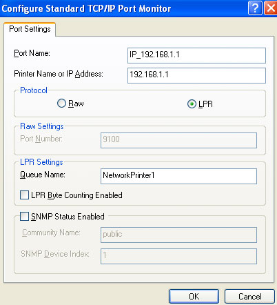
Setting up an LPD Printer in Windows XP
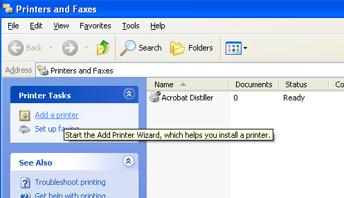
1. Click the Printers and Faxes icon in Control Panel.
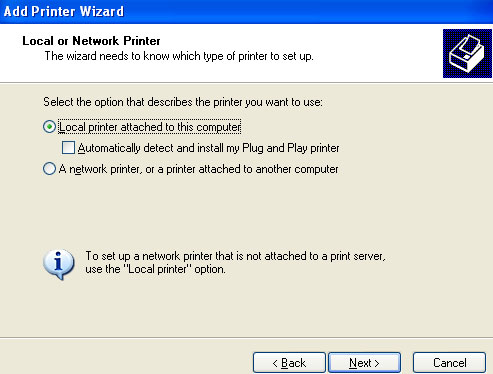
2. Click Add a Printer to activate the Add Printer Wizard and then click Next.
3. Select Local printer attached to this computer. Deselect Automatically detect and install my Plug and Play printer click Next.
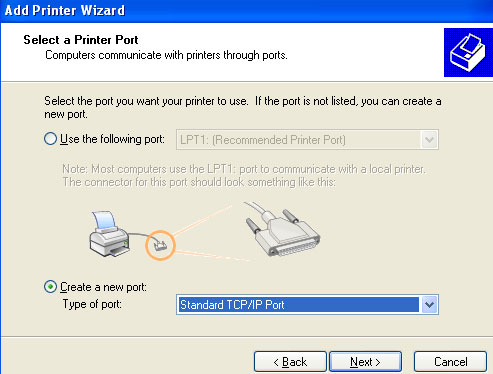
4. In the Select a Printer Port screen, select Create a new port. Select Standard TCP/IP Port in the Type of port dropdown menu. Click Next to activate the Add Standard TCP/IP Printer Port Wizard. Click Next.
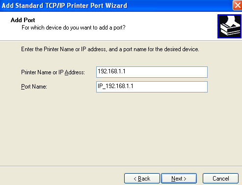
5. Specify 192.168.1.1 in the Printer Name or IP Address and click Next.
6. Select Custom and click Settings. Configure the following parameters:
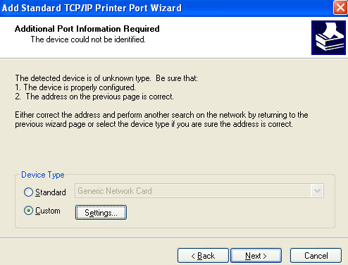
- Select LPR for the protocol.
- Access the Web-based Management console of the USR8200. Click Home
on the side-bar to display the Network Map. Locate the name of the printer
in the Network Map and enter that name in the Queue Name of the Printer
Wizard screen. Click OK.
7. Click Finish. The Add Printer Software wizard will appear.
8. Select your printer manufacturer and model from the lists. If your printer manufacturer or model do not appear in the lists, click Have disk to specify the driver location.
9. Specify the name you want to give the printer and whether you want it to be the default printer.
10. Click Next and then click Next again. Select Yes to print a test page.
11. Click Finish to complete the setup procedure.
Setting up a Microsoft Shared Printer
1. Open the Web-based Management console for the USR8200 by launching a Web browser and entering 192.168.1.1 The disk and printer shares available on the USR8200 will be displayed.
2. Click the printer icon.
3. Follow the instructions displayed by the printer installation wizard.
Restore Defaults
You may sometimes want to restore the USR8200 Firewall/VPN/NAS's factory default settings. This may happen, for example, when you want to build a new network from the beginning, or when you cannot recall changes made to the network and want to go back to the default configuration.
To restore default settings:
- Click the Restore Defaults icon in the Advanced screen of the
Management Console. The Restore Defaults screen will be displayed.
- Click OK to restore the USR8200 Firewall/VPN/NAS's factory default settings.
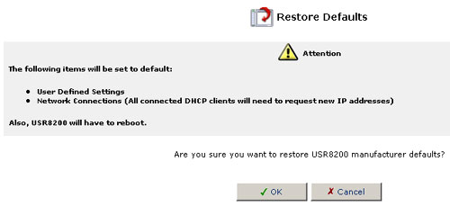
Note: All Web-based settings and management parameters, not only those in the Advanced section, will be restored to their default values. This includes the Administrator password; a user-specified password will no longer be valid.
Restart
To restart your USR8200 Firewall/VPN/NAS:
- Click the Restart icon in the Advanced screen of the Management Console. The Restart screen will be displayed.
- Click OK to restart the USR8200 Firewall/VPN/NAS. This may
take up to one minute. To reenter the Management Console after restarting
the gateway, click the browser's Refresh button.
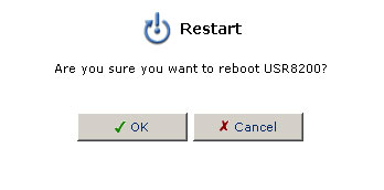
Technical Information
To view technical information regarding the USR8200 Firewall/VPN/NAS:
- Click the Technical Information icon in the Advanced screen
of the Management Console. The Technical Information screen will be
displayed.
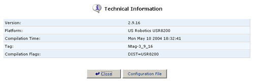
- Click the Configuration File button to view the complete contents of the USR8200 Firewall/VPN/NAS's configuration file.
Using Telnet
The USR8200 Firewall/VPN/NAS supports Telnet. If your computer runs Windows, you can use Telnet by clicking on Start and selecting Run. Enter telnet followed by the IP address of the USR8200 Firewall/VPN/NAS.
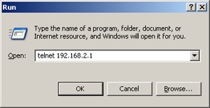
Log in with the user name and password you normally use.
Once you're logged in, you can open a UNIX-like shell by entering the shell command: