These are the options available in the Status menu:
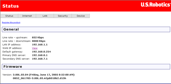
After you log in to the router, the general status page appears:
This page shows, among other things, the router's data transmission and receipt speeds and your ISP's router address. It also contains information on the router's domain name system (DNS) server, which maps URLs such as www.usr.com to four-number IP addresses. You may use this page to check the router’s firmware version before upgrading.
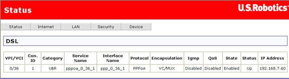
This page details specific connectivity values as directed by your ISP.
Note: If this page does not have values yet, it means that you still need to set up your router. You can do this by running EasyConfigurator. (Windows users: click Windows Start, Programs, and U.S. Robotics EasyConfigurator. Macintosh and Linux users: double-click on the EasyConfigurator icon on the desktop.)
| Item | Description |
| VPI/VCI | DSL connection parameters, similar to an IP address but for an ATM network. |
| Con. ID | A number value indicating the order of connection. |
| Category | This is the class of ATM service (UBR – unspecified bit-rate, VBR – variable bit-rate). |
| Service Name | A name used to define the expected level of service for the access concentrator. (The default is a generic name created by the router and not used.) |
| Interface Name | Table entry name created by the router and used only by the router. |
| Protocol | This is the authentication and encapsulation protocol used over ATM on the ADSL connection. |
| Encapsulation | Encapsulation is a set of rules for building packets. This is the type of ATM encapsulation. |
| IGMP | The router uses the Internet Group Management Protocol to establish host memberships in particular multicast groups on a single network. (One common application of this is with a multicast video stream.) |
| QoS | The router's Quality of Service feature gives high-priority status to certain types of packets (defined by the user). Click here for more information on this. |
| State | This is the connection state (enabled or disabled). |
| Status | The status of the connection — Up means PPP service is running, Down means PPP service it has stopped. |
| IP Address | The router's address obtained from or assigned by your ISP. The router uses this address to communicate with the network outside your local area network. |
Note: If the IP Address field is blank, confirm that your DSL settings are correct. If you are not sure, restore the router to factory defaults by using a thin tool such as a paper clip to press the Reset button on the back of the router for at least five seconds. Then run EasyConfigurator again, paying close attention to the user name and password of the PPP account, supplied by your Internet Service Provider.
The system log screen shows you the system events log, where the router saves data about the various events and problems that occur. You can customise the types of information stored in the log as well as what parts of that information appear when the log is displayed. The page might look like this when you first open it:
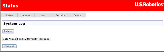
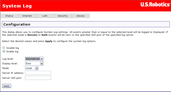
The Configure button is for specifying what type of data you want to display in the log:
| Option | Description |
| Disable log / Enable log | Click on one of these options to disable or enable the recording of log data. |
| Log level | Log Level allows you to configure which types of events are logged. There are several levels of log events:
The router records all log events at the chosen level and above. For instance, if you set the log level to Critical, all critical, alert, and emergency events are logged, but none of the others are recorded. |
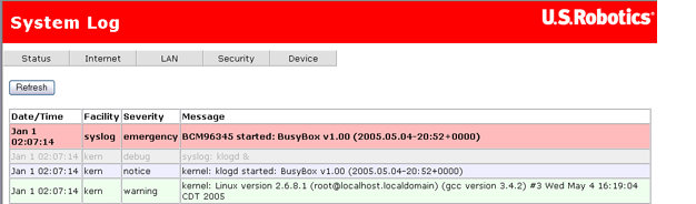
| Display level | This lets you choose the event level to display in the previous System Log page. This item uses the same event level ranking as Log Level above, but it applies to what events are displayed in the WUI rather than recorded. |
| Mode | This lets you specify whether log events should be stored in the router's local memory, be sent to a remote log server, or both simultaneously. If you choose Remote, the system log will not show the events saved on the remote server. The remote server would be a syslog device, which you would need to set up. |
| Server IP address | When you select either Remote mode or Both mode, this is the Internet address of the remote log server. |
| Server UDP port | When you select either Remote mode or Both mode, this is the communication port of the remote log server, to which the router will send log data. By convention, port number 514 is often used, but you can enter any port number you like. |
This status screen summarises the following:
It shows this both for all machines physically connected to the router via cables. You can use the error and drop statistics to troubleshoot communication problems in your local network.
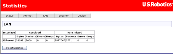
The WAN Statistics page shows the byte transfer, packet transfer, and error statistics for the connection from the router to the Internet. Each line in the table is a different router-Internet connection.

Click Reset Statistics to set the totals back to zero.
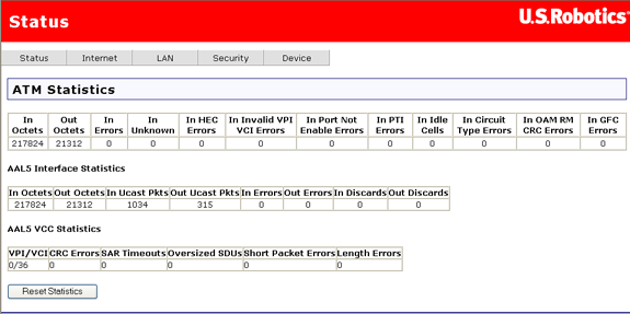
This page shows statistics from the router's low-level ATM protocol.
| Field | Description |
| In Octets | This is the number of octets received by the interface. |
| Out Octets | The number of octets transmitted over the interface. |
| In Errors | The number of cells dropped due to uncorrectable HEC errors. |
| In Unknown | The number of received cells discarded during cell header validation, including cells with unrecognised VPI/VCI values and cells with invalid cell header patterns. If the router is set up to discard cells with undefined PTI values, they are also counted here. |
| In HEC Errors | This is the number of cells received with HEC errors in ATM cell headers. |
| In Invalid VPI VCI Errors | The number of cells received with an unregistered VCC addresses. |
| In Port Not Enabled Errors | The number of cells received on ports that have not been enabled. |
| In PTI Errors | The number of cells received with a payload type indicator (PTI) error in the ATM header. |
| In Idle Cells | This is the number of idle cells received. |
| In Circuit Type Errors | The number of cells received with illegal circuit types. |
| In OAM RM CRC Errors | The number of OAM and RM cells received with cyclic redundancy check (CRC) errors. |
| In GFC Errors | The number of cells received with non-zero GFCs. |
| Field | Description |
| In Octets | This is the number of received AAL5/AAL0 CPCS PDU octets. |
| Out Octets | The number of transmitted AAL5/AAL0 CPCS PDU octets. |
| In Ucast Pkts | The number of received AAL5/AAL0 CPCS PDUs passed to higher layers. |
| Out Ucast Pkts | The number of AAL5/AAL0 CPCS PDUs received for transmission from higher layers. |
| In Errors | This is the number of AAL5/AAL0 CPCS PDUs received that contain errors. The errors include CRC-32 errors, SAR timeouts, and oversized SDUs. |
| Out Errors | The number of AAL5/AAL0 CPCS PDUs that could not be transmitted due to errors. |
| In Discards | The number of AAL5/AAL0 CPCS PDUs discarded due to input buffer overflow. |
| Out Discards | This is the number of AAL5/AAL0 CPCS PDUs discarded without having any errors. (For example, the router could do this to free up buffer space.) |
| Field | Description |
| VPI/VCI | Each row in the third table represents a different VPI/VCI combination. This item is the VPI/VCI for each row. A VPI/VCI combination is sometimes called a VCC (virtual circuit channel). |
| CRC Errors | This is the number of PDUs received with CRC-32 errors. |
| SAR Timeouts | The number of partially-reassembled PDUs discarded because they were not fully reassembled within the required time period. If the re-assembly timer is not supported, this value is zero. |
| Oversized SDUs | The number of PDUs discarded because the corresponding SDUs were too large. |
| Short Packet Errors | This is the number of PDUs discarded because their length was less than the size of the AAL5 trailer. |
| Length Errors | The number of PDUs discarded because the PDU length did not match the length in the AAL5 trailer. |
| Reset button | Click this button to set the totals back to zero. |
This page shows the signal attributes of the router's ADSL connection.
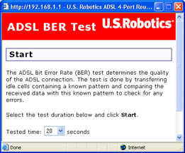
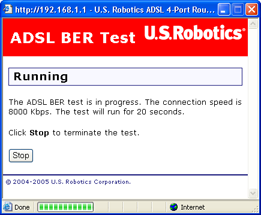
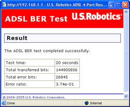
At the bottom of this page, there is a button for running a bit error rate (BER) test. This test determines the quality of the ADSL connection. There is information on this test below the table describing the fields.
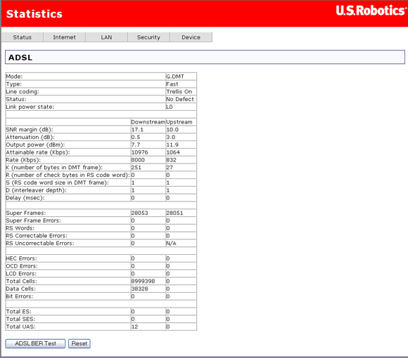
This table describes the fields on the page:
| Field | Description |
| Mode | This is the modulation protocol — G.DMT, T1.413, or G.lite. |
| Type | The channel type, which can be Interleave or Fast. |
| Line coding | This indicates whether Trellis coding is off or on. |
| Status | This is the status of the DSL link. |
| Total ES | This is the total number of "error seconds" — seconds where there was at least one error. |
| Total SES | The total number of "severe error seconds" — seconds with ten or more errors. |
| Total UAS | The number of "unavailable seconds" — seconds when the ADSL link was unavailable. |
| SNR margin (dB) | This is a signal-to-noise ratio (SNR) margin for traffic going in both directions. |
| Attenuation (dB) | An estimate of the average loop attenuation downstream and upstream. |
| Output power (dBm) | The total output power in both directions. |
| Attainable rate | This is the maximum achievable downstream rate. |
| Rate (Kbps) | The actual rate at which data is flowing in both directions. |
| K | This is the number of data bytes in an ADSL data frame. |
| R | The number of redundant check bytes per Reed-Solomon code word. |
| S | The length of the Reed-Solomon code word, in data frames. |
| D | The interleaver depth. |
| Super frames | This is the total number of super frames. |
| Super frame errors | The number of super frames received that had errors. |
| RS words | This is the total number of Reed-Solomon code words. |
| RS correctable errors | The number of Reed-Solomon code words with correctable errors. |
| RS uncorrectable errors | The number of R-S code words that had uncorrectable errors. |
| HEC errors | The total number of header error checksum errors. |
| OCD errors | The number of out-of-cell delineation errors. |
| LCD errors | The total of lost-cell-delineation errors. |
| ES errors | The total extended superframe errors. |
A bit error rate test is available from the ADSL statistics page. Follow this procedure to run a bit error rate test.
Warning: Running this test may cause your ADSL connection to be lost.