
Contents:
Web Diagnostic Interface Reference
Web Diagnostic Interface Reference
In an effort to facilitate the process of installing and diagnosing a modem in the field, the USRobotics Cable Modem Web interface is available to the end user or Multiple System Operator (MSO) field installation technician. The information from this Web interface can be used to make accurate determinations about the operating status of the USRobotics Cable Modem and can also help to troubleshoot most issues that are encountered in the field.
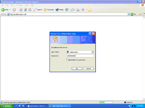
Figure 3 - 1 Web Interface Login
The USRobotics Cable Modem Web interface is available at http://cablemodem.web or at http://192.168.100.13. The http://cablemodem.web instance is available on both registered and nonprovisioned modems.
- The default user ID is "cablemodem"
- The default password is "robotics"
3For code revisions prior to 2.13.6001, the WWW interface is accessible through both the http://cablemodem.web and http;//192.168.100.1. After revision 2.13.6001 it is only accessible via http;//192.168.100.1.
The ability to access this Web interface is evidence that the CPE connection to the cable modem is enabled and properly functioning.
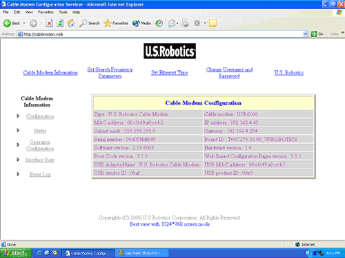
Figure 3 - 2 Configuration
The cable modem Configuration page provides configuration details about the USRobotics Cable Modem, including:
- Type of Modem
- Model Number
- Ethernet MAC Address
- IP Address
- Subnet Mask
- Gateway
- Serial Number
- Board ID
- Software Version
- Hardware Version
- Boot Code Version
- Web Based Configuration Pages Version
- USB Adaptor Name
- USB MAC Address
- USB Vendor ID
- USB Product ID
Status
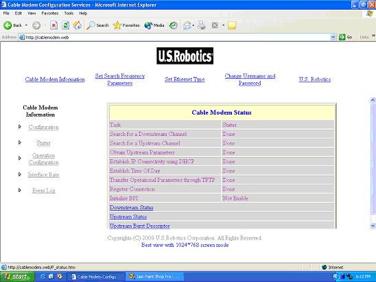
Figure 3 - 3 Status
The cable modem Status page provides the status of the various phases of the DOCSIS provisioning process, such as:
- Search for a Downstream Channel
- Search for an Upstream Channel
- Obtain Upstream Parameters
- Establish IP Connectivity using DHCP
- Establish Time Of Day
- Transfer Operational Parameters through TFTP
- Register Connection
- Initiate BPI
It also provides links to the Downstream Status, Upstream Status, and Upstream Burst Descriptor pages.
Downstream Status
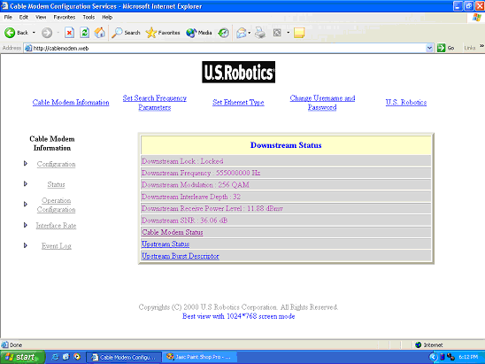
Figure 3 - 4 Downstream Status
The Downstream Status page provides operational details regarding the downstream frequency the USRobotics Cable Modem was able to acquire via the QAM lock process. Details such as:
- Downstream Lock status-Displays whether or not the cable modem has locked to a proper downstream channel.
- Downstream Frequency-Displays the frequency onto which the cable modem has locked.
- Downstream Modulation-Value will either be 64 QAM or 256 QAM.
- Downstream Interleave Depth-The time slot allocation.
- Downstream Receive Power Level-The input level to the cable modem.
- Downstream SNR-The Signal to Noise Ratio.
It also provides links to the Cable Modem Status, Upstream Status, and Upstream Burst Descriptor pages.
Upstream Status
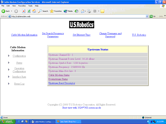
Figure 3 - 5 Upstream Status
The Upstream Status page provides details regarding the upstream channel on which the USRobotics Cable Modem was able to successfully range and register.
- Upstream Channel ID-The CMTS assigned upstream channel number.
- Upstream Transmit Power Level-The level at which the cable modem is transmitting.
- Upstream Symbol Rate-Maximum upstream speed.
- Upstream Frequency-The frequency on which the cable modem is transmitting.
- Upstream Mini-Slot Size-A scheduling function assigned by the CMTS.
The page also provides links to the Cable Modem Status, Downstream Status, and Upstream Burst Descriptor pages.
Upstream Burst Status
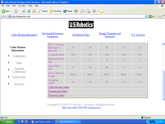
Figure 3 - 6 Upstream Burst Status
The Upstream Burst Status page provides details regarding all available upstreams the USRobotics Cable Modem is able to determine are available from the CMTS.
- FEC Codeword Information Bytes (k)
- Scrambler Seed
- Maximum Burst Size
- Guard Time Size
- Last Codeword Length
- Scrambler on/off
It also provides links to the Cable Modem Status, Downstream Status, and Upstream Status pages.
Operational Configuration
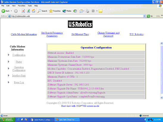
Figure 3 - 7 Operational Configuration
The Operational Configuration page provides the operational details for which the USRobotics Cable Modem has been configured. This information is a combination of details acquired through the provisioning and registration processes.
- Network Access-Enables the modem to communicate on the Internet.
- Maximum Downstream Data Rate-The maximum speed the modem can receive.
- Maximum Upstream Data Rate-The maximum speed the modem can transmit.
- Maximum Upstream Channel Burst-A burst can be faster than the actual data rate.
- Modem Capability-Upstream transmit parameters set.
- DHCP Server IP Address
- Maximum Number of CPEs-The number of clients authorized on the cable modem.
- BPI-Base Line Privacy Interface
- Software Upgrade Server-The sever where new software images reside.
- Software Upgrade File Name-The name of software loaded to the cable modem.
- Software Upgrade AdminStatus-Indicates whether the modem can be upgraded from management or provisioning.
- Software Upgrade OperStatus-Displays whether feature is enabled or disabled.
Interface Rate
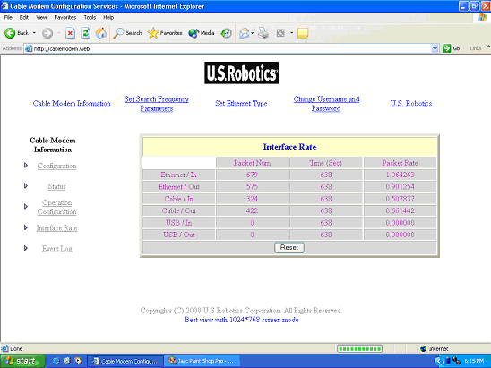
Figure 3 - 8 Interface Rate
The Interface Rate page displays the cumulative count of packets, in each direction, of each interface for the time that the cable modem is powered on or since the last reset. The Packet Rate is simply the number of packets divided by the seconds. This page refreshes every few seconds.
- Ethernet/In
- Ethernet/Out
- Cable/In
- Cable/Out
- USB/In
- USB/Out
Set Search Frequency Parameters
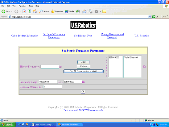
Figure 3 - 9 Set Search Frequency Parameters
The Set Search Frequency Parameters page is available to the MSO for the purpose of eliminating or reducing the time required to scan for a downstream channel. The table to the right of the frame is a history of downstream channels that have previously provided QAM lock. This history is maintained through successive power cycles. The USRobotics Cable Modem will always refer to this table and attempt to QAM lock known, good frequencies before scanning the entire frequency range. If the MSO wishes to reduce the amount of time that it takes to scan, range, and register, entering the exact frequencies of active DOCSIS downstreams in this table is the most direct method of accomplishing this.
