
Contents:
USRobotics SureConnect ADSL
Ethernet/USB Router User Guide
Windows 95, 98, NT 4.0, Me, 2000, XP or later,
Mac and Linux
Terminal User Interface
Overview
The Terminal User Interface (TUI) is one of three router user interfaces. The other interfaces are the Web User Interface (WUI) and Command Line Interface (CLI). Each interface allows you to set up, modify, and view router configuration variables and operational data.
The Terminal User Interface is a system of hierarchical, character-based menus. See the nearby overview for a graphic map of the interface.
Each menu presents options and prompts you for a response. Options occupy most of a menu screen. The bottom of the screen provides information about expected responses…
- Mandatory vs. optional
- Allowable formats
- Operation success or failure
- Error messages
- Directions on what to do next
This document often refers to menu screens with path notation. For example, consider the example in the following table…
| The Desired Action |
The Process |
The Path Notation |
|
Access PPPoA configuration menu from Main Menu screen. |
Choose 2 for ‘ADVANCED’, 7 for ‘SNDCP’, 3 for ‘PPPoA’, and 2 for ‘CONFIGURE PPPoA’. |
Main Menu=>Advanced=> SNDCP=>PPPoA=> Configure PPPoA |
Screen shots best describe some menu options. In this manual, a description precedes each screen shot. Afterward, the manual provides definitions of screen variables. Pages without screen shots include a menu path, followed by a description and necessary definitions.
Accessing the Terminal User Interface
To access the Terminal User Interface, follow these steps…
- Connect a console cable between a computer and the router.
- Launch a terminal emulation program.
- Configure the terminal emulation program as follows…
• Terminal Type: VT-100
• Parity: None
• Bits Per Second: 9600
• Stop Bits: 1
• Data Bits: 8
• Flow Control: None
- Turn on the router. Configuration messages appear as the router boots up.
- Allow the default configuration to load.
- When prompted, type in the User Name and Password. The default user name is Root. The default password is 12345.
| Terminal User Interface Map
|
Main Menu
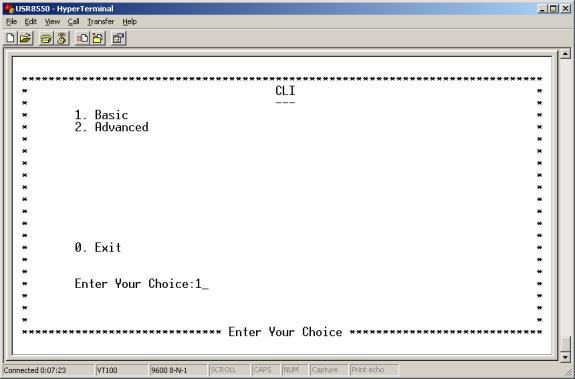
The Main Menu is the first or top-level menu in the Terminal User Interface. The Main Menu presents you with three options…
- Enter 1 to open the to the Basic Menu.
- Enter 2 to open the Advanced Menu.
- Enter 0 to exit the Terminal User Interface.
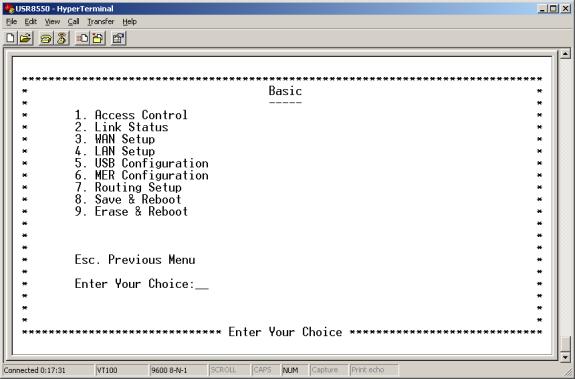
Basic
Enter 1 at the Main Menu. The Basic Menu appears. This menu includes the following options…
Main Menu=>Basic=>
Access Control
Enter 1 at the Basic Menu. The Access Control Menu appears. This menu provides the following options…
• List Users. Lists currently defined users by type, and provides associated services. The user “root” is the default administrative login for the router.
• Configure User. Opens the Configure User Menu, which allows you to add or delete users. Add users to enforce ACL (Access Control List) and proxy services. Options include…
| § User Name |
§ Password |
| § Permissions (admin / ordinary) |
• Delete User. Allows you to delete users by user name.
• Change Password. Allows you to change a user’s password. Options include…
|
§ User Name |
§ Old Password |
|
§ New Password |
§ Confirm Password |
Main Menu=>Basic=>
Link Status
Enter 2 at the Basic Menu. The Link Status Menu appears. This menu displays current link status. Link status parameters include…
Link Status Parameters
Status Term |
Meaning |
| ADSL Line Status |
Displays the current ADSL line status |
| ADSL Standard |
Displays the ADSL standard within the current configuration. The standards are: MULTI, T1.413, G.dmt, and G.Lite. |
| UpStream |
Displays the upstream data rate, as negotiated by DSL link (KB/s) |
|
DownStream |
Displays the downstream data rate, as negotiated by DSL link (KB/s) |
|
Attenuation |
Displays the current attenuation in decibels |
|
SNR Margin |
Displays the current SNR margin in decibels |
| HEC Count |
Displays the number of ATM cells received with errors since start of link. |
| Firmware |
Displays the version number of the firmware |
| 15 min ES Counter |
Displays the number of errors per second for the current 15-minute period |
|
CRC Errors |
Displays the number of cyclical redundancy check errors per second since training |
| 1 day ES Counter |
Displays the number of errors per second for the current day |
Main Menu=>Basic=>
WAN Setup
Enter 3 at the Basic Menu. The WAN Setup Menu appears. This menu allows you list, configure, or delete ATM PVCs. Each option takes you to another screen.
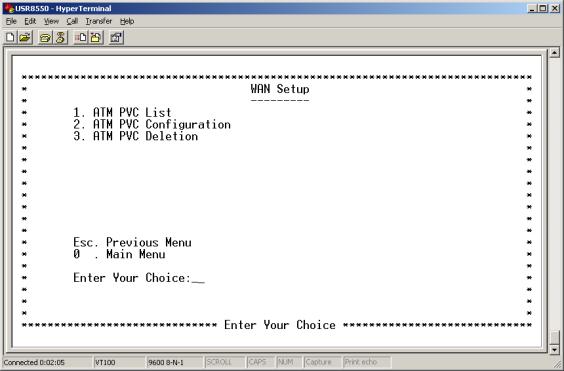
• ATM PVC List. Enter 1 at the WAN Setup Menu. The ATM PVC List Menu appears. This menu displays a list of currently defined PVCs.
• ATM PVC Configuration. Enter 2 at the WAN Setup Menu. The ATM PVC Configuration Menu appears. To configure an ATM PVC…
- Enter a 2 on the WAN Setup Menu. The ATM PVC Configuration Menu appears.
- Enter VPI and VCI data…
- Five Subnetwork Dependent Convergence Protocol (SNDCP) options appear. (Bridge / Routed / PPPoE / PPPoA / MER)
- Choose the SNDCP option provided by your DSL service provider. Next, SNDCP options for the SNDCP that you selected appear. Subsequent screens present several options for each SNDCP.
- Enter the required information…
| § VPI [0-255] § VCI [0-65,535] § SNDCP Component ( ) § [Bridge / Routed / PPPoE / PPPoA / MER] § Encap [vc / 11c] § Nat [Enable / Disable] § WAN IP Address ( ) |
§ Subnet Mask ( ) § User Name § Password § Mode [Auto / Direct] § Idle Timeout [min] § Authentication ( ) § [pap / chap / mschapv1 / mschapv2] § DHCP Server ( ) |
Main Menu=>Basic=>
WAN Setup (continued) 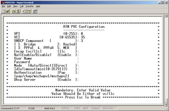
§ Bridge
A. For a bridge PVC, enter a 1 at SNDCP Component.
B. Enter the encapsulation type (vc or 11c).
§ Routed
A. Enter SNDCP option 2 for routed.
B. Choose the encapsulation method.
C. Choose to enable or disable the NAT.
D. Configure the WAN IP Address.
E. Configure the subnet mask.
§ PPPoE
A. Enter SNDCP option 3 for PPPoE.
B. Enter remaining information as provided by your DSL service provider.
§ PPPoA
A. Enter SNDCP option 4 for PPPoA.
B. Enter remaining information as provided by your DSL service provider.
§ MER
A. Enter SNDCP option 5 for MER.
B. Enter remaining information as provided by your DSL service provider.
- After you complete your configuration, proceed to the Basic Menu and enter 8. The Save & Reboot Menu appears. From this menu, save your changes and reboot the router.
Main Menu=>Basic=>
WAN Setup (continued)• ATM PVC Deletion.
Enter 3 at the WAN Setup Menu. The ATM PVC Deletion Menu appears. To delete an ATM PVC…
- Enter valid VPI and VCI values.
- After you complete your configuration, proceed to the Basic Menu and enter 8. The Save & Reboot Menu appears. From this menu, save your changes and reboot the router.
Main Menu=>Basic=>
LAN Setup
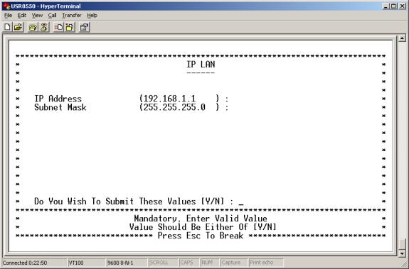
Enter 4 at the Basic Menu. The IP LAN Menu appears. To configure a LAN IP address…
- Accept default values or enter new IP address and subnet mask values.
- Use LAN Setup to set the router’s IP Address and Subnet Mask.
- Setup the LAN IP address to connect the router to.
- Manage the router from your Local Area Network (LAN). A LAN connects computers in the same building or area.
- After you complete your configuration, proceed to the Basic Menu and enter 8. The Save & Reboot Menu appears. From this menu, save your changes and reboot the router.
IP addresses deliver packets of data across a network. These addresses differentiate the source and destination IP address and keep them constant. When a router port detects a packet, the router checks the routing table. The port attempts to match the network number of the destination IP address with its routing table entry. If the port finds a match, it forwards the packet to the destination network. With no match, the port forwards the packet to a router defined as the default gateway.
Subnet masks split one network into a set of mini networks or subnets. Subnetting helps to reduce traffic on each subnet. Subnetting also makes the network more manageable. Each subnet functions as if it were an independent network.
Main Menu=>Basic=>
USB Configuration
Enter 5 at the Basic Menu. The Configure USB Interface Menu appears. To configure the USB interface…
- Enter a valid IP Address.
- Enter a valid subnet mask.
- After you complete your configuration, proceed to the Basic Menu and enter 8. The Save & Reboot Menu appears. From this menu, save your changes and reboot the router.

Main Menu=>Basic=>
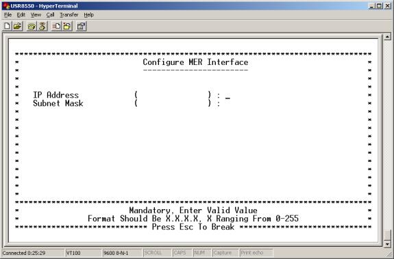
MER Configuration
Enter 6 at the Basic Menu. The Configure MER Menu appears. To configure the MER interface…
- Enter a valid subnet mask.
- After you complete your configuration, proceed to the Basic Menu and enter 8. The Save & Reboot Menu appears. From this menu, save your changes and reboot the router.
Main Menu=>Basic=>
Routing Setup
Enter 7 at the Basic Menu. The Routing Setup Menu appears. The Routing Setup menu provides seven menu options. These options allow you to configure a route.
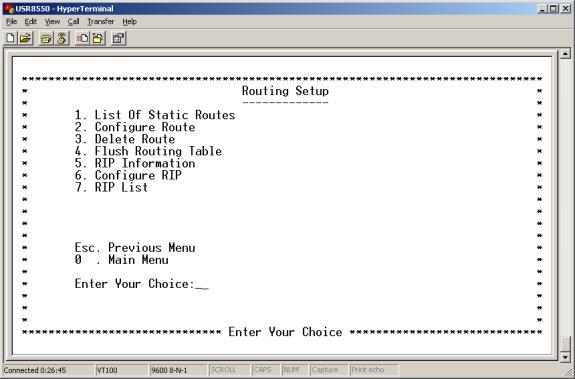
- List Of Static Routes. Enter 1 at the Routing Setup Menu. The List of Static Routes Menu appears. This menu lists defined static routes by Network ID address, subnet mask, and next hop address.
- Configure Route. Enter 2 at the Routing Setup Menu. The Configure Route Menu appears. From this menu, you can add new static routes. A router forwards data packets between local area networks (LANs) or wide area networks (WANs). Based on routing tables and routing protocols, routers read the network address in each transmitted frame. Routers then decide how to send the frame. A router bases this decision on the best route. The Configure Route Menu allows you to adjust how the router forwards received IP packets.
To configure a route…
- Enter a valid destination network ID. This is the network IP designation of the network defined in the table.
- Enter a valid destination subnet mask. This is the network subnet mask of the entry defined in the table.
- Enter a valid next hop ID. This is the IP address or gateway that the router uses to arrive at the destination address.
- After you complete your configuration, proceed to the Basic Menu and enter 8. The Save & Reboot Menu appears. From this menu, save your changes and reboot the router.
Main Menu=>Basic=>
Routing Setup (continued)
• Delete Route. Enter 3 at the Routing Setup Menu. The Delete Route Menu appears. From this menu, you can delete a route. To delete a route…
1. Enter the appropriate network ID.
2. Enter subnet mask data.
3. After you complete your configuration, proceed to the Basic Menu and enter 8. The Save & Reboot Menu appears. From this menu, save your changes and reboot the router.
• Flush Routing Table. Enter 4 at the Routing Setup Menu. The Flush Routing Table Menu appears. To flush a routing table…
1. Type Y.
2. After you complete your configuration, proceed to the Basic Menu and enter 8. The Save & Reboot Menu appears. From this menu, save your changes and reboot the router.
• RIP Information.Enter 5 at the Routing Setup Menu. The RIP Information Menu appears. This menu lists currently configured RIP information.
• Configure RIP. Enter 6 at the Routing Setup Menu. The Configure RIP Menu appears. Use this menu to turn RIP on or off. Also use the menu to define which RIP version to use. Routing Information Protocol (RIP) is a routing protocol and is part of the TCP/IP suite. RIP plots a route based on the smallest hop count between source and destination. RIP determines the smallest hop count by communicating with other routers in the network. Only use RIP if the target router also utilizes RIP.To set up a route…
1. Enter the RIP status. Set RIP Status to either “on” or “off.”
2. Enter a number for the version. Either set RIP Version to 1 (for RIP1) or 2 (for RIP2). The version number must match the RIP version that other routers in the network use.
3. After you complete your configuration, proceed to the Basic Menu and enter 8. The Save & Reboot Menu appears. From this menu, save your changes and reboot the router.
• RIP List. Enter 7 at the Routing Setup Menu. The RIP List Menu appears. This menu displays routes that the RIP has learned. You’ll see an empty list if RIP is off or if the router hasn’t learned any routes.
Main Menu=>Basic=>
Save & Reboot
Enter 8 at the Basic Menu. The Save & Reboot Menu appears. This menu allows you to save the current configuration and reboot the router.
Main Menu=>Basic=>
Erase & Reboot
Enter 9 at the Basic Menu. The Erase & Reboot Menu appears. This menu allows you to erase the saved configuration and reboot the router.
Main Menu=>
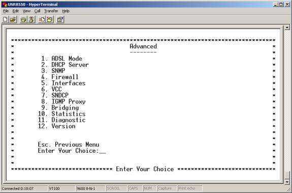
Advanced
Enter 2 at the Main Menu. The Advanced Menu appears. This menu provides the following options…
Main Menu=>Advanced=>
Enter 1 at the Advanced Menu. The ADSL Mode Menu appears. This menu allows you to read or write configuration and management variables, or configure the ADSL mode. The router uses configuration and management variables (CMV) to tweak performance and provide management functions. Router firmware defines these values.
| !
|
CAUTION Don’t write configuration and management variables unless you receive explicit instructions to do so. Alteration of CMV values can adversely affect router performance. |
| !
|
CAUTION Leave ADSL mode values alone unless you receive specific instructions on what to do. Alteration of the ADSL mode can adversely affect router performance. |
Main Menu=>Advanced=>
DHCP Server
Enter 2 at the Advanced Menu. The DHCP Server Menu appears. DHCP stands for Dynamic Host Configuration Protocol. This protocol dynamically assigns IP addresses and related information to Local Area Network (LAN) nodes. For temporarily connected network users, DHCP provides safe, reliable, and simple TCP/IP network configuration. DHCP confers these benefits by preventing address conflicts and conserving IP address use. To conserve address use, DHCP centralizes address allocation.
The DHCP Server menu provides the following options…
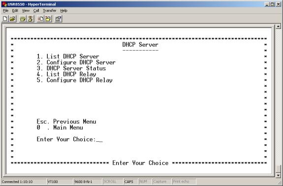
- List DHCP Server. Enter 1 at the DHCP Server Menu. The List DHCP Server Menu appears. This menu provides a list of currently configured DHCP servers and associated variables.
- Configure DHCP Server. Enter 2 at the DHCP Server Menu. The Configure DHCP Server Menu appears. To configure a DHCP server…
- Choose an Ethernet interface. The remaining DHCP options appear on the screen.
- Create a new DHCP server for the selected interface by entering legal values for each variable. See DHCP variables below.
- Set the following parameters…
DHCP Parameters
DHCP Term
Definition
Interface
LAN port that the DHCP server will support.
Starting IP Address
First IP address provided on a LAN port node’s DHCP request.
End IP Address
Last IP address in the pool provided on a LAN port node’s DHCP request.
Gateway
IP address of the Default Gateway or Router that the node will use.
Netmask
Subnet Mask for the LAN that the node will be on.
DNS
Domain Name Server. Actually, here we aren’t referring to the DNS itself. Instead, we refer to the IP address of the DNS that the node will use. DNS is a server with a database. The database translates a domain name into a corresponding IP address. For example, “USR.com” resolves into IP address 231.222.320.04. Use this address to communicate over the LAN between the node and USR.com web site.
Lease Time
Number of days that the node can use a DHCP lease. Subsequently, you must renew the lease with the DHCP server.
- After you complete your configuration, proceed to the Basic Menu and enter 8. The Save & Reboot Menu appears. From this menu, save your changes and reboot the router.
Main Menu=>Advanced=>
DHCP Server (continued)
- DHCP Server Status. Enter 3 at the DHCP Server Menu. The DHCP Server Status Menu appears. This menu displays current DHCP server status. The menu also allows you to enable, disable, or delete DHCP servers.
- List DHCP Relay. Enter 4 at the DHCP Server Menu. The List DHCP Relay Menu appears. This menu displays DHCP Relay information.
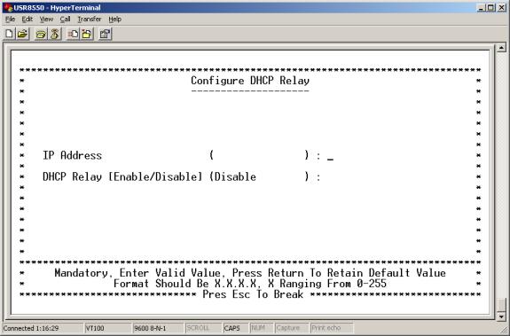
- Configure DHCP Relay. Enter 5 at the DHCP Server Menu. The DHCP Server Status Menu appears. This menu allows you to configure DHCP relay functions. Suppose that a Dynamic Host Configuration Protocol (DHCP) server resides on a different LAN than the node broadcasting for DHCP service. Then the DHCP broadcast request must be forwarded across the router/WAN to a subnet where a DHCP server resides. To assure receipt of an IP address that corresponds to this subnet, the router relays DHCP. The router must have a record of the DHCP server’s IP address. With this address, the router can direct the request to the DHCP server’s appropriate input IP address.
To configure a DHCP relay, follow these steps…
1. On the Configure DHCP Relay Menu, input the IP address of DHCP server.
2. Enable the relay agent.
3. After you complete your configuration, proceed to the Basic Menu and enter 8. The Save & Reboot Menu appears. From this menu, save your changes and reboot the router.
Main Menu=>Advanced=>
SNMPEnter 3 at the Advanced Menu. The SNMP Menu appears. This menu provides the following options…
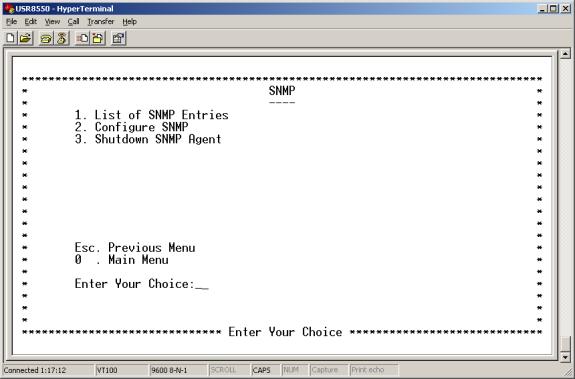
- List of SNMP Entries. Enter 1 at the SNMP Menu. The SNMP Entries Menu appears. This menu lists your SNMP variable settings.
- Configure SNMP. Enter 2 at the SNMP Menu. The Configure SNMP Menu appears. This menu allows you to configure SNMP variables.
- Enter VPI and VCI data…
| § System Version description ( ) § System Contact ( ) |
§ System Location ( ) |
- After you complete your configuration, proceed to the Basic Menu and enter 8. The Save & Reboot Menu appears. From this menu, save your changes and reboot the router.
- Shutdown SNMP Agent. Enter 3 at the SNMP Menu. The Shutdown SNMP Agent Menu appears. This menu allows you to shut down the SNMP agent.
Main Menu=>Advanced=>
Enter 4 at the Advanced Menu. The Firewall Menu appears. This menu provides the following options…
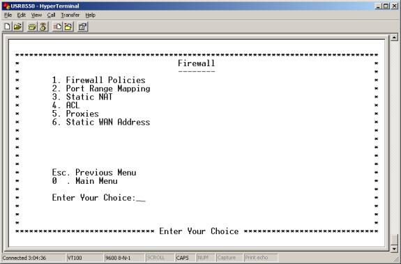
- Firewall Policies. Enter 1 at the Firewall Menu. The Firewall Policies Menu appears. Select Policies or Action, or press <ESC> to exit to the previous menu.
Main Menu=>Advanced=>Firewall=>Firewall Policies=>
Policies
Enter 1 at the Firewall Policies Menu. The Policies Menu appears. This menu allows you to add, list, or delete port firewall policies.
- Add Firewall Policy. Enter 1 at the Policies Menu. The Firewall Add Policies Menu appears. To add a firewall policy, set the following parameters…
Firewall Policy Parameters
| Policy Term |
Definition |
|
Precedence |
Priority of the policy that you’re creating. Options range from 0 to 65,535. |
|
Src IP Address |
Data source. Either an IP address or network. |
|
Src Net Mask |
Subnet Mask for the data’s network source. Options range from /12 (255.240.0.0) to /32 (255.255.255.255). |
|
Dest IP Address |
Data destination. Either an IP address or network. |
|
Dest Net Mask |
Subnet Mask for the data’s network destination. Options range from /12 (255.240.0.0) to /32 (255.255.255.255). |
|
Source Port |
Transport layer source port. Options range from 0 to 65,535. |
|
Protocol |
IP protocols to be filtered. Options are: Any (all), TCP, UDP, ICMP, AH, ESP. |
|
TCP Flags |
Filtering of the TCP Flags that control session setup and termination. Options are: None, urg (Urgent), ack (acknowledgment), psh (push), rst (reset), syn (synchronize), fin (finished). |
After you complete your configuration, proceed to the Basic Menu and enter 8. The Save & Reboot Menu appears. From this menu, save your changes and reboot the router.
- List Firewall Policies. Enter 2 at the Policies Menu. The List Firewall Policies Menu appears. This menu displays implemented firewall policies. Press <ENTER> to see the next page in the list.
- Delete Firewall Policies. Enter 3 at the Policies Menu. The Delete Firewall Policies Menu appears. This menu allows you to delete Firewall policies.
Main Menu=>Advanced=>Firewall=>Firewall Policies=>
Action
Enter 2 at the Firewall Policies Menu. The Action Menu appears. This menu allows you to add, list, or delete firewall actions.
- Add Firewall Action. Enter 1 at the Action Menu. The Firewall Action Add Menu appears. To add a firewall action, set the following parameters…
Firewall Action Parameters
| Policy Term |
Definition |
|
|
Interface Name |
Name of the Interface to apply the parameter to. |
|
|
Direction |
Specifies whether the action applies to incoming, outgoing, or both incoming and outgoing traffic. Options are Any, In, and Out. |
|
|
FW Action |
How the system handles packets. Your sub-options include… |
|
|
Allow |
Permits packets to enter or leave the system. |
|
|
Reset |
Forces the TCP connection to reset |
|
|
Reject |
Drops the packet and issues an “unreach host” ICMP error. |
|
|
Deny |
Drops the packet. |
|
|
Time |
The parameter applies during the time period that you specify. Select the start (From) day, time and stop (To) day and time. |
|
After you complete your configuration, proceed to the Basic Menu and enter 8. The Save & Reboot Menu appears. From this menu, save your changes and reboot the router.
- List Firewall Action. Enter 2 at the Action Menu. The Firewall Action List Menu appears. This menu displays implemented firewall actions.
- Delete Firewall Action. Enter 3 at the Action Menu. The Firewall Action Add Menu appears. This menu allows you to delete Firewall actions.
Main Menu=>Advanced=>Firewall=>
Port Range MappingEnter 2 at the Firewall Menu. The Port Range Mapping Menu appears. This menu allows you to add, list or delete port range mapping.
- Add. Enter 1 at the Port Range Mapping Menu. The Add Menu appears. This menu allows you to add port range mapping entries. NAT stands for Network Address Translation. NAT enhances the power of Port Range Mapping. Together, they can map a local IP address and port to a public IP address and port. To add a port range entry, enter starting and ending addresses to map them to a single public address.
To add a port range entry, set the following parameters…
Port Range Mapping Parameters
| Port Range Term |
Definition |
|
Public Address |
Set the public, destination IP address inside a packet header. The router will map or redirect packets with the address that you specify. |
|
Public Port From |
Set the first (From) port of the public address that the router maps or redirects. Options range from 1 to 65,535. |
|
Public Port To |
Set the last (To) port of the public address that the router maps or redirects. Options range from 1 to 65,535. |
|
Local Address |
Set the IP address of a machine on the local LAN. The router directs packets to this address. |
|
Local Port From |
Set the first (From) port of the local address that the router uses. Options range from 1 to 65,535. |
|
Local Port To |
Set the last (To) port of the local address that the router uses. Options range from 1 to 65,535. |
|
Protocol |
Set protocol. Your protocol setting applies to the other parameters on this page. Your options are TCP or UDP port numbers. |
After you complete your configuration, proceed to the Basic Menu and enter 8. The Save & Reboot Menu appears. From this menu, save your changes and reboot the router.
- List. Enter 2 at the Port Range Mapping Menu. The List Menu appears. This menu displays configured port mapping entries. If you find an empty list, then you haven’t defined any entries.
- Delete. Enter 3 at the Port Range Mapping Menu. The Delete Menu appears. This menu allows you to delete port range mapping entries.
Main Menu=>Advanced=>Firewall=>
Static NATEnter 1 at the Firewall Menu. The Static NAT Menu appears. This menu allows you to add, list, or delete Static NAT entries. Static NAT stands for Static Network Address Translation. Static NAT maps local IP addresses to a public IP address.
- Add. Enter 1 at the Static NAT Menu. The Add Menu appears. This menu allows you to add Static NAT entries. To add a Static NAT entry, set the following parameters…
Static NAT Parameters
| Static NAT Term |
Definition |
|
Local Address From |
First address in a range of local IP addresses. The router maps these addresses to the public IP address. |
|
Local Address To |
Last address in a range of local IP addresses. The router maps these addresses to the public IP address. |
|
NAT Public Address |
Public address. The router maps local addresses to this public address. |
After you complete your configuration, proceed to the Basic Menu and enter 8. The Save & Reboot Menu appears. From this menu, save your changes and reboot the router.
- List. Enter 2 at the Static NAT Menu. The List Menu appears. This menu displays implemented static NAT entries. If you find an empty list, then you haven’t defined any entries.
- Delete. Enter 3 at the Static NAT Menu. The Delete Menu appears. To delete a Static NAT entry, enter the starting local address.
Main Menu=>Advanced=>Firewall=>
Enter 4 at the Firewall Menu. The ACL Menu appears. This menu allows you to add, list, or delete ACL entries. ACL provides setup for Proxy services. From the Proxy Configuration Menu, you can enable or disable proxy services.
Proxy Services are specialized application programs. These programs accept users’ requests from LAN clients for Internet services like FTP and HTTP. On behalf of LAN clients, the programs then set up connections to servers on the WAN. A proxy server authenticates against the user database. This server filters the request against the Access Control List. The server forwards requests to actual services. Proxy Servers are application specific. Each application needs its own proxy server.
- Add ACL/FTP. Enter 1 at the ACL Menu. The ACL Configuration Menu appears. This menu allows you to set FTP ACL variables. Options after “User Name” depend on whether you enter “FTP” or “HTTP.” See ACL variables after the http example.
ACL Parameters
| Static NAT Term |
Definition |
|
Application (Port) |
Proxy port to configure. Options are FTP or HTTP. |
|
Priority |
Priority of the policy you’re creating. Options range from 0 to 65,535. |
|
User Name |
A configured user in the router’s internal database. You must configure users through the Telnet CLI with the “adduser” command. |
|
MIME Type |
HTTP application file type (MIME) to filter or proxy. Options are… •application (all), •image (all), •video (all), •audio (all), •application/octet-stream, •audio/x-wav, •audio/x-mpeg, •image/jpeg, •video/mpeg. |
|
Method |
FTP command to filter or proxy. Options are Get and Put. |
|
Domain Name |
Address of an Internet site to filter. |
|
Destination Address |
Destination IP address of the FTP or HTTP server on the WAN. |
|
URL (Uniform Resource Locator) |
Addresses that define the route to a file on the Web or Internet facility. Enter the URL to filter. |
|
Source Range |
Local IP address range that the rule applies to. “From” is the first IP address in the range. “To” is the last IP address in the range. |
|
Day From/To |
Set the effective start (From) day and time for the policy. Set the effective stop (To) day and time for the policy. |
|
Action |
Specifies how the ACL deals with requests to the policy. Options are Allow or Deny. |
After you complete your configuration, proceed to the Basic Menu and enter 8. The Save & Reboot Menu appears. From this menu, save your changes and reboot the router.
- List ACL. Enter 2 at the ACL Menu. The ACL List Menu appears. This menu displays variables associated with currently defined ACLs.
- Delete ACL. Enter 3 at the ACL Menu. The ACL Delete Menu appears. To delete an ACL entry, enter the application type and rule ID.
Main Menu=>Advanced=>Firewall=>
Enter 5 at the Firewall Menu. The Proxies Menu appears. This menu allows you to configure a proxy.
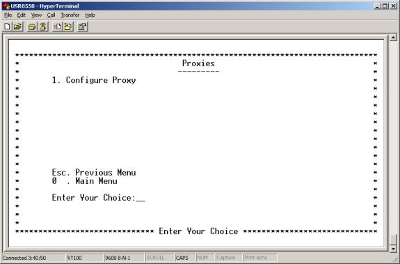
- Configure Proxy. Enter 1 at the Proxy Menu. The Proxy Configuration Menu appears. This menu allows you to enable or disable ftp or http proxies. See the ACL menu for more information on Proxy setup.
Main Menu=>Advanced=>Firewall=>
Static WAN Address
Enter 6 at the Firewall Menu. The Static WAN Address Menu appears. This menu allows you to add, list or delete static WAN addresses.
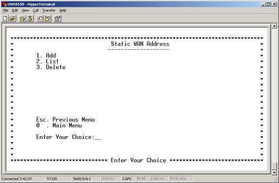
- Add. Enter 1 at the Static WAN Address Menu. The Add Static WAN Address Menu appears. This menu allows you to use a static WAN IP address. Enter the IP address of the WAN.
- List. Enter 2 at the Static WAN Address Menu. The List Static WAN Address Menu appears. This menu displays applied static WAN IP address.
- Delete. Enter 3 at the Static WAN Address Menu. The Delete Static WAN Address Menu appears. This menu allows you to delete static WAN IP addresses.
Main Menu=>Advanced=>
Interfaces
Enter 5 at the Advanced Menu. The Interfaces Menu appears. This menu provides the following options…
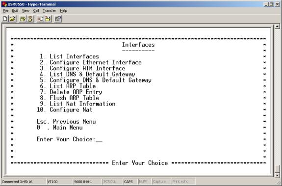
- List Interfaces. Enter 1 at the Interfaces Menu. The List Interfaces Menu appears. This menu displays defined interfaces. Press <ENTER> to view the next page of the list.
- Configure Ethernet Interface. Enter 2 at the Interfaces Menu. The Configure Ethernet Interface Menu appears. This menu provides the following options…
• Configure IP Address. Enter 1 at the Configure Ethernet Interface Menu. The Configure IP Address Menu appears. This menu allows you to assign IP data and interface status to either Ethernet interface. Options include…
| § Interface Name [eth0 / eth1] |
§ IP Address Type [static / dynamic] |
| § IP Address |
§ Subnet Mask |
| § Broadcast |
§ MTU |
| § Status [up / down] |
• Configure MAC, Speed & Type. Enter 2 at the Configure Ethernet Interface Menu. The Configure Mac Speed & Type Menu appears. This menu allows you to assign MAC address variables to either Ethernet interface.
| § Interface Name [eth0 / eth1] |
§ Speed [10 / 100 / auto] |
| § MAC Address |
§ Type [full / half / auto ] |
Main Menu=>Advanced=>
Interfaces (continued)
• Configure ATM Interface. Enter 3 at the Interfaces Menu. The Configure ATM Interface Menu appears. This menu allows you to configure an ATM interface. Enter the desired ATM interface name. A menu presents additional variables…
| § Interface Name [ atm[0-7] ] |
§ Broadcast |
| § IP Address Type [static / dynamic] |
§ Alias Address |
| § IP Address |
§ MTU |
| § Subnet Mask |
§ Status [up / down] |
• List DNS & Default Gateway. Enter 4 at the Interfaces Menu. The List DNS & Default Gateway Menu appears. This menu displays currently configured DNS and default gateway server information.
• Configure DNS & Default Gateway. Enter 5 at the Interfaces Menu. The Configure DNA & Default Gateway Menu appears. This menu allows you to set DNS and default gateway variables. When the router functions as a Network Address Port Translation (NAPT) device, the router uses DNS relay settings. With these settings, the router forwards DNS requests from a LAN node to a known DNS server. Normally, the requests arrive at a DNS server over the WAN link. See DNS variables below.
To configure a DNS and default gateway, set the following parameters…
DNS & Default Gateway Parameters
| DNS Term |
Definition |
|
Domain Name |
Internet site address that the router is a group of (i.e. usr.com). |
|
IP address of the Primary DNS that the router will use. Domain Name Server (DNS) is a server with a database. This server translates a domain name into the corresponding IP address. For example, USR.com resolves into IP address 231.222.320.04. Use this address to communicate over the LAN between the node and web site USR.com. |
|
|
Secondary DNS Server |
IP address of the Secondary DNS that the router will use. |
|
Gateway |
IP address of the Default Gateway the Router is to use. |
|
DNS Relay |
Enabling or Disabling router ability to convey a DNS request from a LAN node. In this case, the node is on a DNS server at the WAN link. |
After you complete your configuration, proceed to the Basic Menu and enter 8. The Save & Reboot Menu appears. From this menu, save your changes and reboot the router.
- List ARP Table. Enter 6 at the Interfaces Menu. The List ARP Table Menu appears. This menu displays ARP table values.
- Delete ARP Entry. Enter 7 at the Interfaces Menu. The Delete ARP Entry Menu appears. This menu allows you to delete ARP table values. Enter the IP address of the ARP table value that you desire to delete.
- Flush ARP Table. Enter 8 at the Interfaces Menu. The Configure DNA & Default Gateway Menu appears. This menu allows you to flush ARP table values.
Main Menu=>Advanced=>
Interfaces (continued)
- List Nat Information. Enter 9 at the Interfaces Menu. The List NAT Information Menu appears. This menu displays currently configured NAT variables. If you see a ‘NAT Not Configured’ message, it means that you haven’t defined any variables.
- Configure Nat. Enter 10 at the Interfaces Menu. The Configure DNA & Default Gateway Menu appears. This menu allows you to enable Nat on specific interfaces. Set “Enable Nat” to yes or no. If you set it to yes, then select one of these interface options…
| § eth1 |
§ ppp [0-7] |
| § atm |
§ mer0 |
Main Menu=>Advanced=>
VCC
Enter 6 at the Advanced Menu. The VCC Menu appears. This menu allows you to list, add, list, or delete VCC.
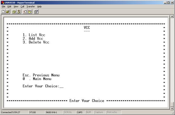
- List VCC. Enter 1 at the VCC Menu. The List VCC Menu appears. This menu displays defined VCC variables.
- Add VCC. Enter 2 at the VCC Menu. The Add VCC Menu appears. This menu allows you to add VCC variables. Enter VPI, VCI, encapsulation, and service. Afterward, the system presents additional options. Here is an example of settings for a UBR. Other service options present similar variables. To add VCC variables, set these interface options...
| § Vpi [0-255] |
§ Peak Cell Rate {cells/sec} |
| § Vci [0-65,535] |
§ Average Cell Rate {cells/sec} |
| § Encapsulation Type [aa15] |
§ Burst Size {in cells} |
| § Service [cbr/rtvbr/nrtvbr/ubr] |
§ CDVT {in micro sec} |
After you complete your configuration, proceed to the Basic Menu and enter 8. The Save & Reboot Menu appears. From this menu, save your changes and reboot the router.
• Delete VCC. Enter 3 at the VCC Menu. The Delete VCC Menu appears. This menu Allows you to delete VCC variables.
Main Menu=>Advanced=>
Enter 7 at the Advanced Menu. The SNDCAP Menu appears. This menu provides the following options...
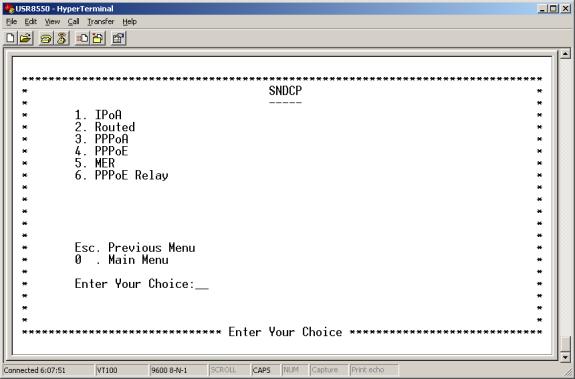
- IPoA. Enter 1 at the SNDCP Menu. The IPoA Menu appears. This menu allows you to list IPoA variables. You can also configure IPoA variables by VCC and interface. To add IPoA variables, set these options...
| § Vpi [0-255] |
§ Default PVC [Y/N] |
| § Vci [0-65,535] |
§ Next Hop IP Address |
| § Interface Name [ atm [0-7] ] |
§ Status [enable/disable] |
| § Encapsulation Type [aa15] |
After you complete your configuration, proceed to the Basic Menu and enter 8. The Save & Reboot Menu appears. From this menu, save your changes and reboot the router.
- Routed. Enter 2 at the SNDCP Menu. The Routed Menu appears. This menu allows you to list routed variables. You can also configure routed variables by setting these options...
| § Vpi [0-255] |
§ Encapsulation Type [11c/vc] |
| § Vci [0-65,535] |
§ Status [enable/disable] |
| § Interface Name [ ATM [0-7] ] |
After you complete your configuration, proceed to the Basic Menu and enter 8. The Save & Reboot Menu appears. From this menu, save your changes and reboot the router.
Main Menu=>Advanced=>SNDCP=>PPPoA
Enter 3 at the SNDCP Menu. The PPPoA Menu appears. This menu provides the following options…
- List PPPoA. Enter 1 at the PPPoA Menu. The List PPPoA Menu appears. This menu displays configured PPPoA variables.
- Configure PPPoA. Enter 2 at the PPPoA Menu. The PPPoA Menu appears. This is a two-screen menu. Set these PPPoA variables...
|
Configure PPPoA, Screen 1 |
Configure PPPoA, Screen 2 |
| § Profile ID [0-7] |
§ MTU [0-1,500] |
| § Interface Name [ ppp [0-7] ] |
§ Encapsulation Type [11c/vc] |
| § Vpi [0-255] |
§ Restart Time |
| § Vci [0-65,535] |
§ My IP Address |
| § User Name |
§ Peer IP Address |
| § Password |
§ Enable Nat [Y/N] |
| § Authentication Protocol [pap/chap] |
§ NetMask |
| § MRU [0-1,500] |
After you complete your configuration, proceed to the Basic Menu and enter 8. The Save & Reboot Menu appears. From this menu, save your changes and reboot the router.
• Start PPPoA. Enter 3 at the PPPoA Menu. The Start PPPoA Menu appears. This menu allows you to start a PPPoA session by entering the session’s profile ID.
• Stop PPPoA. Enter 4 at the PPPoA Menu. The Stop PPPoA Menu appears. This menu allows you to stop a PPPoA session by providing the session’s profile ID.
• Delete PPPoA. Enter 5 at the PPPoA Menu. The Delete PPPoA Menu appears. This menu allows you to delete a PPPoA session by entering the session’s profile ID.
• Default PPPoA. Enter 6 at the PPPoA Menu. The Default PPPoA Menu appears. This menu allows you to make a PPPoA session the default session by providing the session’s profile ID.
Main Menu=>Advanced=>SNDCP=>
PPPoE
Enter 4 at the SNDCP Menu. The PPPoE Menu appears. This menu provides the following options…
- List PPPoE. Enter 1 at the PPPoE Menu. The List PPPoE Menu appears. This menu displays configured PPPoE variables.
- Configure PPPoE. Enter 2 at the PPPoE Menu. The Configure PPPoE Menu appears. This is a two-screen menu. Set these PPPoE variables...
|
Configure PPPoE, Screen 1 |
Configure PPPoE, Screen 2 |
| § Profile ID [0-7] |
§ Restart Time |
| § Interface Name [ ppp [0-7] ] |
§ Mode [Auto/Direct] |
| § Vpi [0-255] |
§ Idle Timeout |
| § Vci [0-65,535] |
§ My IP Address |
| § Encapsulation Type [11c/vc] |
§ Peer IP Address |
| § User Name |
§ Service Name |
| § Password |
§ AC Name |
| § Authentication Protocol [pap/chap/mschapv1/mschapv2] |
§ Host Unique Tag [Y/N] |
| § MRU [0-1,492] |
§ Ether Address |
| § MTU [0-1,492] |
§ Enable Nat [Y/N] |
| § |
§ SubnetMask |
After you complete your configuration, proceed to the Basic Menu and enter 8. The Save & Reboot Menu appears. From this menu, save your changes and reboot the router.
• Start PPPoE. Enter 3 at the PPPoE Menu. The Start PPPoE Menu appears. This menu allows you to start a PPPoE session by entering the session’s profile ID.
• Stop PPPoE. Enter 4 at the PPPoE Menu. The Stop PPPoE Menu appears. This menu allows you to stop a PPPoE session by providing the session’s profile ID.
• Delete PPPoE. Enter 5 at the PPPoE Menu. The Delete PPPoE Menu appears. This menu allows you to delete a PPPoE session by entering the session’s profile ID.
• Default PPPoE. Enter 6 at the PPPoE Menu. The Default PPPoE Menu appears. This menu allows you to make a PPPoE session the default session by providing the session’s profile ID.
Main Menu=>Advanced=>SNDCP=>
MER
Enter 5 at the SNDCP Menu. The PPPoE Menu appears. This menu provides the following options…
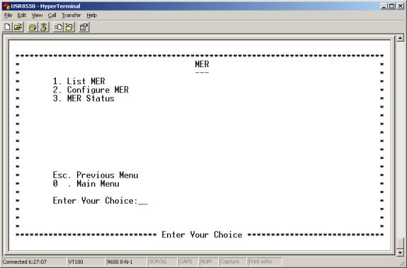
- List MER. Enter 1 at the MER Menu. The List MER Menu appears. This menu displays configured MER variables.
- Configure MER. Enter 2 at the MER Menu. The Configure MER Menu appears. This menu allows you to set MER variables. To configure MER variables, set these options...
| § Interface Name [mer0] |
§ Vci [0-65,535] |
| § Vpi [0-255] |
§ Encapsulation Type [11c/vc] |
After you complete your configuration, proceed to the Basic Menu and enter 8. The Save & Reboot Menu appears. From this menu, save your changes and reboot the router.
• MER Status. Enter 3 at the MER Menu. The MER Status Menu appears. This menu allows you to change between enabled, disabled, or deleted status.
Main Menu=>Advanced=>SNDCP=>
PPPoE Relay
Enter 6 at the SNDCAP Menu. The PPPoE Relay Menu appears. This menu allows you to list, configure, or delete PPPoE relays. From this menu, you can also check the status of a PPPoE relay.
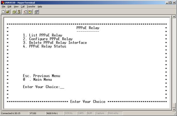
- List PPPoE Relay. Enter 1 at the PPPoE Relay Menu. The List PPPoE Relay Menu appears. This menu displays variables for configured PPPoE relays.
- Configure PPPoE Relay. Enter 2 at the PPPoE Relay Menu. The Configure PPPoE Relay Menu appears. This menu allows you to set PPPoE relay variables. To configure PPPoE relay variables, set these options...
| § Client Interface [eth0/eth1/ATM/usb0] |
§ Vpi [0-255] |
| § Server Interface [eth0/eth1/ATM/usb0] |
§ Vci [0-65,535] |
After you complete your configuration, proceed to the Basic Menu and enter 8. The Save & Reboot Menu appears. From this menu, save your changes and reboot the router.
• Delete PPPoE Relay Interface. Enter 3 at the PPPoE Relay Menu. The Delete PPPoE Relay Menu appears. This menu allows you to delete PPPoE Relay interfaces by providing an interface name.
• PPPoE Relay Status.
Enter 4 at the PPPoE Relay Menu. The PPPoE Relay Status Menu appears. This menu allows you to change PPPoE Relay Status between enabled and disabled.
Main Menu=>Advanced=>
IGMP Proxy
Enter 8 at the Advanced Menu. The IGMP Proxy Menu appears. This menu allows you to list, configure, or delete proxy interfaces.
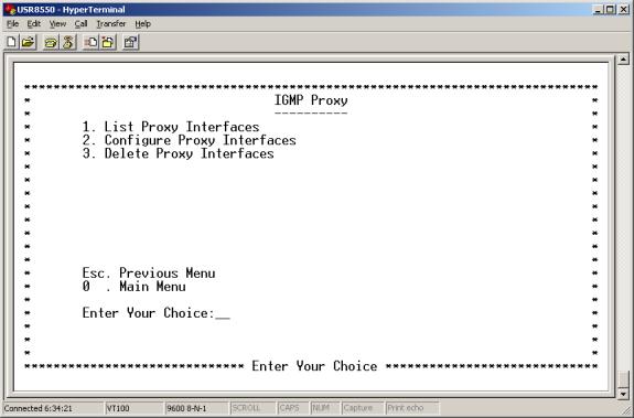
- List Proxy Interfaces. Enter 1 at the IGMP Proxy Menu. The List Proxy Interfaces Menu appears. This menu displays configured proxy interface variables.
- Configure Proxy Interfaces. Enter 2 at the IGMP Proxy Menu. The Configure Proxy Interfaces Menu appears. This menu allows you to set proxy Interface variables. To configure configure proxy interfaces, set these options...
| § Proxy Interface eth [0-1] / ATM [0-7] / ppp [0-7] |
§ Router Interface eth [0-1] / ATM [0-7] / ppp [0-7] |
After you complete your configuration, proceed to the Basic Menu and enter 8. The Save & Reboot Menu appears. From this menu, save your changes and reboot the router.
- Delete Proxy Interfaces. Enter 3 at the IGMP Proxy Menu. The Delete Proxy Interfaces Menu appears. This menu allows you to delete proxy interfaces by providing a specific interface name.
Main Menu=>Advanced=>
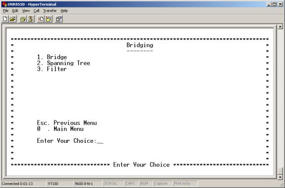
Bridging
Enter 9 at the Advanced Menu. The Bridging Menu appears. This menu provides the following options…
Main Menu=>Advanced=>Bridging=>
Bridge
Enter 1 at the Bridging Menu. The Bridge Menu appears. This menu provides the following options…
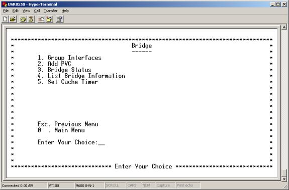
- Group Interfaces. Enter 1 at the Bridge Menu. The Group Interfaces Menu appears. This menu allows you to enter interface names to group interfaces. For each interface, select an interface type. Each menu line item refers to another group interface. A line item looks like this…
| Interface Name1 [ [eth [0-1] / ATM [0-7] / usb [0] ] |
- Add PVC. Enter 2 at the Bridge Menu. The Add PVC Menu appears. This menu allows you to add a PVC by entering interface name, VCC, and encapsulation type variables.
- Bridge Status. Enter 3 at the Bridge Menu. The Bridge Status Menu appears. This menu allows you to change bridge status between enabled, disabled, and deleted.
- List Bridge Information. Enter 4 at the Bridge Menu. The List Bridge Information Menu appears. This menu displays configured bridge information. Press <ENTER> to view the next list page.
- Set Cache Timer. Enter 5 at the Bridge Menu. The Set Cache Timer Menu appears. This menu allows you to configure cache timer variables.
Spanning Tree
Spanning Tree. Enter 2 at the Bridging Menu. The Spanning Tree Menu appears. This menu allows you to Provides the following options.
- Configure Bridge Port. Enter 1 at the Spanning Tree Menu. The Set Cache Timer Menu appears. This menu allows you to set these Spanning Tree Bridge Port variables…
|
• Interface Name [ eth[0-1]/ATM[0-7] ] |
• Link Cost |
|
• Priority |
After you complete your configuration, proceed to the Basic Menu and enter 8. The Save & Reboot Menu appears. From this menu, save your changes and reboot the router.
Transparent bridges use the spanning tree algorithm to dynamically determine the best source-to-destination path. This algorithm avoids bridge loops (multiple paths linking one segment to another) within a network. The algorithm determines all redundant paths and makes only one of them active. The spanning tree protocol (STP) is part of the IEEE 802.1 standard.
- Configure Bridge Parms. Enter 2 at the Spanning Tree Menu. The Configure Bridge Parms Menu appears. To configure a spanning tree bridge from this menu, set the following parameters…
Bridge Parameters
| Bridge Term |
Definition |
|
Interface Name |
Router interface to be configured for spanning tree. |
|
Link Cost |
Cost associated with that interface. Based on this cost, the bridge decides which link to forward data over. The options range from 0 to 65,535. |
|
Port Priority |
Determines which port becomes the root port. Options range from 0 to 255. |
|
Bridge Priority |
Determines which bridge becomes the root bridge. Options range from 0 to 65,000. |
|
Max Age Time |
All bridges in the bridged LAN use this timeout value. The root sets Max Age value. Options range from 1 to 60 seconds. |
|
Hello Time |
Time interval between generations of configuration BPDUs. The root generates configuration BPDUs. Options range from 1 to 10 seconds. |
|
Forward Delay Time |
All bridges in the bridged LAN use this timeout value. The root sets the forward delay value. Options range from 1 to 200 seconds. |
After you complete your configuration, proceed to the Basic Menu and enter 8. The Save & Reboot Menu appears. From this menu, save your changes and reboot the router.
- Spanning Tree Status. Enter 3 at the Spanning Tree Menu. The Spanning Tree Status Menu appears. This menu allows you to enable or disable Spanning Tree status.
- List Spanning Tree Info. Enter 4 at the Spanning Tree Menu. The List Spanning Tree Info Menu appears. This menu displays configured Spanning Tree variables.
Main Menu=>Advanced=>Bridging=>
Enter 3 at the Bridging Menu. The Filter Menu appears. This menu allows you to list, configure, delete, or flush filters.
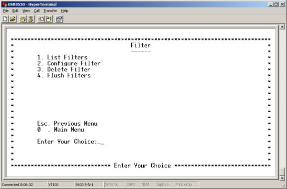
- List Filters. Enter 1 at the Filter Menu. The List Filters Menu appears. This menu displays defined filter variables.
- Configure Filter. Enter 2 at the Filter Menu. The Configure Filter Menu appears. This menu allows you to set filter variables. The MAC address is a unique serial number burned into Ethernet adapters. This address distinguishes this network card from others. MAC Filters allow or reject WAN access for specific machines. To configure a filter from this menu, set the following parameters…
MAC Parameters
| MAC Term |
Definition |
|
MAC Address |
Static MAC address to add to the table. |
|
Filter Action |
What the router should do with a data frame from this MAC address. The options are Forward or Drop. |
After you complete your configuration, proceed to the Basic Menu and enter 8. The Save & Reboot Menu appears. From this menu, save your changes and reboot the router.
- Delete Filter. Enter 3 at the Filter Menu. The Delete Filter Menu appears. This menu allows you to delete filters by entering their MAC addresses.
- Flush Filter. Enter 4 at the Filter Menu. The Flush Filter Menu appears. This menu allows you to flush currently configured filters.
Statistics
Enter 10 at the Advanced Menu. The Statistics Menu appears. This menu provides the following options…
- Interface. Enter 1 at the Statistics Menu. The Interface Menu appears. This menu displays interface statistics. The table below defines interface parameters.
Interface Parameters
| Interface Term |
Meaning |
| Interface Name |
Name of the interface |
|
Admin Status |
Indicates whether the interface is up or down |
|
Octets In |
Number of received octets (in bytes) |
|
Unicast PktsIn |
Number of received unicast packets |
|
Broadcast PktsIn |
Number of received broadcast packets |
|
Discards In |
Number of received and discarded packets |
|
Errors In |
Number of received errors |
|
Octets Out |
Number of transmitted octets (in bytes) |
|
Unicast PktsOut |
Number of transmitted unicast packets |
|
Broadcast PktsOut |
Number of transmitted broadcast packets |
|
Discards Out |
Number of transmitted and discarded packets |
|
Errors Out |
Number of transmitted errors |
- TCP-IP. Enter 2 at the Statistics Menu. The Interface Menu appears. This menu displays TCP/IP statistics.
- DHCP-Lease. Enter 3 at the Statistics Menu. The DHCP Lease Menu appears. This menu displays DHCP statistics. With no active DHCP leases, the list is empty.
- AAL5. Enter 4 at the Statistics Menu. The AAL5 Menu appears. This menu displays ATM AAL5 statistics.
- SNDCP. Enter 5 at the Statistics Menu. The SNDCP Menu appears. This menu displays packet information for the permanent virtual circuit (PVC). The system organizes the list by encapsulation method.
- Bridge. Enter 6 at the Statistics Menu. The Bridge Menu appears. This menu displays bridge statistics.
- Firewall Statistics. Enter 7 at the Statistics Menu. The Firewall Statistics Menu appears. This menu provides the following options…
- Flow Statistics.
Enter 1 at the Statistics Menu. The Firewall Statistics Menu appears. This menu displays firewall flow statistics. - FTP Statistics.
Enter 2 at the Statistics Menu. The Firewall Statistics Menu appears. This menu displays FTP Proxy statistics. - HTTP Statistics.
Enter 3 at the Statistics Menu. The Firewall Statistics Menu appears. This menu displays HTTP Proxy statistics.
Main Menu=>Advanced=>
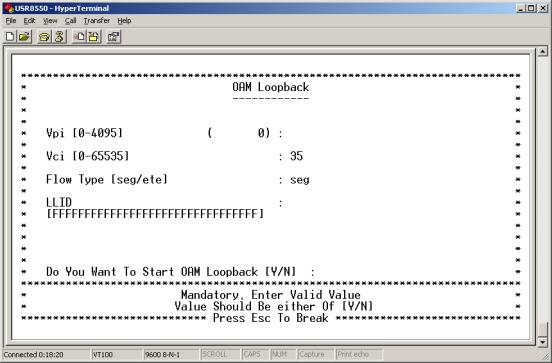
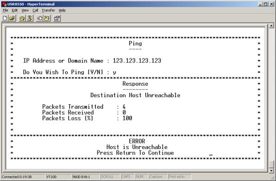
Diagnostic
Enter 11 at the Advanced Menu. The Diagnostic Menu appears. To perform an OAM loopback test on a VCC, enter 1. To perform a ping test, enter 2.
Main Menu=>Advanced=>
VersionEnter 12 at the Advanced Menu. The Version Menu appears. This menu provides software version information for your router.