Contents:
EasyConfigurator Advanced Features
Web User Interface
USRobotics SureConnect
ADSL
4-Port Router User Guide
Windows 95, 98, NT 4.0, Me,
2000, XP
Macintosh and Linux
Web User Interface
Device Configuration
Begin Quick Setup
Service Provider Settings
Network
Security
Tools
Statistics
Overview
The Web User Interface (WUI) allows you to set up, modify, and view router configuration variables and operational data.
-
If the ADSL router is not on, turn on the power. Wait about one minute.
-
In a Web browser on the PC, connect to http://192.168.1.1/ to enter the router's configuration program. The browser should connect and you should see the Enter Network Password screen shown below.
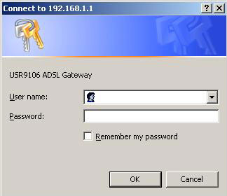
Type admin in the User Name and Password fields, and click OK. These values can be changed later in the Web User Interface (WUI).
Restoring Factory Default Settings
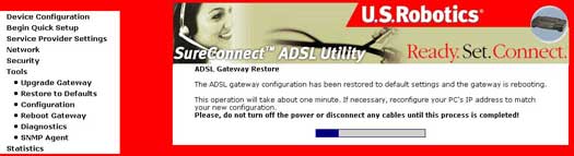
It is only necessary to restore the router to the factory default settings when the router is in a non-functioning state or you wish to reprogram completely. In the majority of cases, your router is already configured to the default values. The factory default configuration can be restored either by pushing the reset button for more than five seconds, or by clicking the Restore Default Configuration option in the Restore Settings screen.
The following default settings are present when setting up the router for the first time.
- LAN port IP address: 192.168.1.1
- WAN connection type: bridging
- WAN ATM PVC encapsulation: LLC
- Local administrator account name: admin
- Local administrator account password: admin
- Local non-administrator account name: user
- Local non-administrator account password: user
- Remote WAN access: disabled
- Remote WAN access account name: support
- Remote WAN access account password: support
- NAT and Firewall: disabled
- DHCP server on LAN interface: enabled
- WAN IP address: none
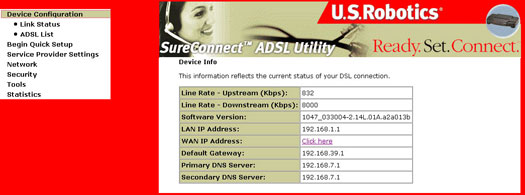
Device Configuration
After login, the Device Info screen appears:
>
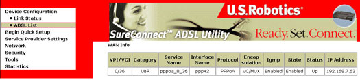
ADSL List
The ADSL List screen details specific connectivity values as directed by your ISP.
>
Status LEDs

The USRobotics SureConnect ADSL 4-Port Router has seven LEDs on the front of the router: PWR, Ethernet 1, 2, 3, 4, ADSL, and WAN IP. The operational status of the router is indicated by the LED conditions listed below.
| PWR | On Green | Power is being received from the AC power adapter. |
| Off | No power is detected. | |
| WAN IP | On Green | The router gets a public IP Address from the Internet Service Provider (ISP), in PPP mode. |
| Flashing Green | IP connected and passing data. | |
| Red | Failed to get IP Address from ISP. | |
| Off | ADSL is not synchronized or in bridge mode. | |
| Ethernet 1,2,3,4 | On Green | A physical connection between the router and the computer has been established and detected through the Ethernet cable. |
| Flashing Green | Data traffic is flowing. | |
| Off | A physical connection between the router and the computer has not been established through the Ethernet cable. | |
| ADSL | On Green | A DSL link has been established. |
| Flashing Green | A DSL link is being negotiated. | |
| Off | The DSL link has failed. |
Begin Quick Setup
Begin Quick Setup allows the user to configure the ADSL router for DSL connectivity and Internet access. It also guides the user through the ISP network setup first and then the home or office network setup. The USRobotics SureConnect ADSL 4-Port Router supports the following five ISP network operating modes over router ADSL interface:
- PPP over Ethernet (PPPoE)
- PPP over ATM (PPPoA)
- MAC Encapsulated Routing (MER)
- IP over ATM (IPoA)
- Bridging
The ISP network operating mode operation depends on the service provider's configuration on the Central Office side and Broadband Access Server (BRAS) for your ADSL line.
Your ISP should be able to provide the following, if needed:
- VPI/VCI values
- ADSL Standard (Modulation)
- Encapsulation Mode
- Authentication (PAP or CHAP) for PPP connections
The following configuration considerations apply:
- If the service provider provides PPPoE service, then the connection selection depends on whether the LAN-side device (typically a PC) is running a PPPoE client or whether the 4-Port Router is to run the PPPoE client. The 4-Port Router ADSL router can support both cases simultaneously. Consult your ISP instructions on the appropriate protocol to use.
- NAPT and Firewall are always enabled when PPPoE or PPPoA mode is selected, but they can be enabled or disabled by the user when MER or IPoA mode is selected. NAPT and Firewall are always disabled when Bridge mode is selected.
- Depending on the network operating mode, and whether NAPT and Firewall are enabled or disabled, the main panel will display or hide the NAPT/Firewall menu. For instance, at initial setup, the default network operating mode is Bridge. The main panel will not show the NAPT and Firewall menu.
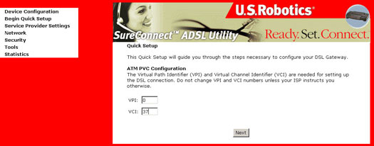
- Click Begin Quick Setup to start the setup process.
- Enter the appropriate VPI and VCI and click Next. The valid VPI range is from 0 to 255. The valid VCI range is from 32 to 65535.
Connection Type
The Connection Type screen allows you to select the type of network protocol over the ATM PVC supported by the Internet Service Provider. Refer to the beginning of this section for a bridge description of these protocols.
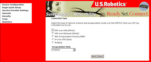
Select the protocol as assigned by your ISP and proceed to the matching sections in this manual for further instructions.
PPP over ATM (PPPoA) / PPP over Ethernet (PPPoE)
- Select the PPP over ATM (PPPoA) or PPP over Ethernet (PPPoE) radio button and click Next.
- Select the appropriate Encapsulation Mode. The following screen appears:
- Allows only one PC on the LAN
- The public IP address assigned by the remote using the PPP/IPCP protocol is actually not used on the WAN PPP interface. Instead, it is forwarded to the PC's LAN interface through DHCP. Only one PC on the LAN can be connected to the remote since the DHCP server within the ADSL router has only a single IP address to assign to a LAN device.
- NAPT and firewall are disabled when this option is selected.
- The ADSL router becomes the default gateway and DNS server to the PC through DHCP using the LAN interface IP address.
- The ADSL router extends the IP subnet at the remote service provider to the LAN PC. That is, the PC becomes a host belonging to the same IP subnet.
- The ADSL router bridges the IP packets between WAN and LAN ports, unless the packet is addressed to the router's LAN IP address.
- After entering your settings, click Next. The following screen appears:
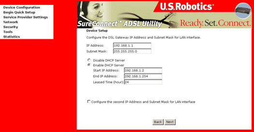
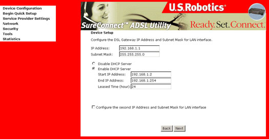
- This page allows the user to configure the LAN interface IP address, subnetmask and DHCP server, if the user would like this ADSL router to assign dynamic IP addresses, DNS server and default gateways to other LAN devices. Select the button Enable DHCP server on the LAN to enter the starting IP address and end IP address and DHCP lease time. Click Next after completion. The following screen appears:
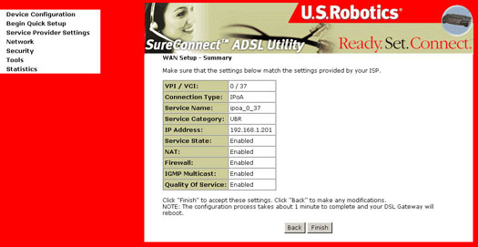
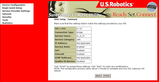
- The Network Setup - Summary Screen presents the entire configuration summary. Click Finish if the settings are correct.
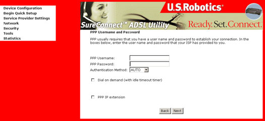
The screen provides fields to enter the PPP Username and the PPP Password. The password requirement is dependent on the particular requirements of the ISP or the ADSL service provider.
The WUI allows a maximum of 256 characters in the PPP user name and a maximum of 32 characters in PPP password.
The 4-Port Router can be configured to disconnect if there is no activity for a specific period of time by selecting the Disconnect if no activity check box.
The entered value must be between 1 minute to 4320 minutes. Default is 30 minutes. The PPP IP Extension is a special feature deployed by some service providers. Unless your service provider specifically requires this setup, do not select it.
The PPP IP Extension supports the following conditions:
After clicking Finish, the router will save the configuration to delete memory and reboot. The WUI will not respond until the system is brought up again. After the system is up, close the Web browser and relaunch another Web browser session.
MAC Encapsulated Routing (MER)
To configure MER, do the following:
- Select the MAC Encapsulated Routing (MER) radio button.
- Select the appropriate Encapsulation Mode and click Next. The following screen appears:
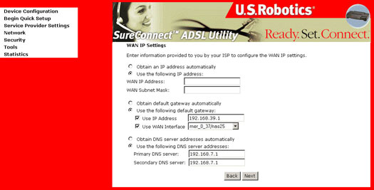
- If IP addressing can be obtained automatically through the DHCP client in the ADSL router, select Obtain an IP address automatically; otherwise, the user must enter the WAN interface IP address, subnet mask, and default gateway address.
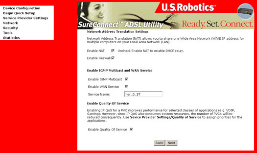
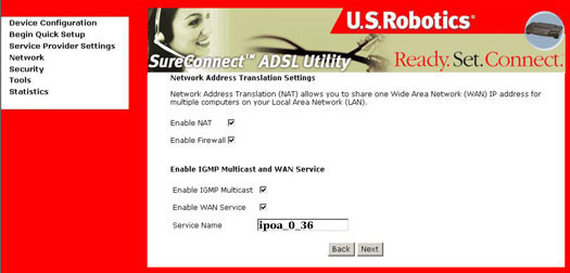
- Enable NAT checkbox: If the LAN is configured with a private IP address, the user should select this checkbox. If a private IP address is not used on the LAN side, this checkbox should be deselected.
- Enable Firewall checkbox: If the firewall checkbox is selected, the user can configure firewall features after the system comes up from the reboot. If firewall is not used, this checkbox should be de-selected.
- Assuming you prefer to use both the Enable NAT and Enable Firewall settings, click Next.
- To use the DHCP service
on the LAN, select the Enable DHCP server on the LAN check box
and enter the Start IP address, the End IP address, and DHCP lease time.
This configures the router to automatically assign IP addresses, default
gateway address, and DNS server addresses to each of your PCs.
- After completion, click Next.
- The Network Setup - Summary Screen presents the entire configuration summary. Click Finish to complete the configuration (which requires about 1 minute to complete) or Back to change any of the settings.
The values that must be entered in the fields should be provided by the ISP.
If DNS server addresses can be obtained automatically through the DHCP, select Obtain DNS server address automatically; otherwise, the user must enter the preferred DNS server address and the optional alternative DNS server address and click Next. The following screen appears:

When the configuration is completed and the unit has rebooted, the 4-Port Router is ready for operation and the LEDs display as described in the LED description tables.
IP over ATM (IPoA)
To configure IP over ATM (IPoA), do the following.
- Select the IP over ATM (IPoA) radio button.
- Select the appropriate Encapsulation Mode and click Next.
Notice that DHCP client is not supported over IPoA. The user must enter the WAN interface IP address, the remote end IP address for the default gateway setup, and the DNS server addresses provided by the ISP and click Next. The following screen appears:
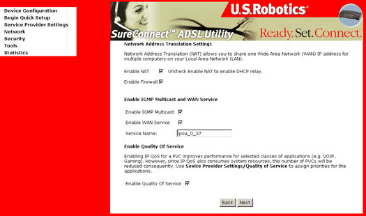
- Enable NAT checkbox: If the LAN is configured with a private IP address, the user should select this checkbox. If a private IP address is not used on the LAN side, this checkbox should be deselected to free up system resources for better performance.
- Enable Firewall checkbox: If the firewall checkbox is selected, the user can configure firewall features after the system comes up from the reboot. If firewall is not used, this checkbox should be de-selected to free up system resources for better performance.
Assuming you prefer to use both the Enable NAT and Enable Firewall settings, click Next. The following screen appears.
- To use the DHCP service
on the LAN, select the Enable DHCP server on the LAN check box
and enter the Start IP address, the End IP address, and the DHCP lease
time. This configures the router to automatically assign IP addresses,
default gateway address, and DNS server addresses to each of your PCs.

- After completion, click Next. The following screen appears:
- The Network Setup - Summary Screen presents the entire configuration summary. Click Finish to complete the configuration (which requires about 1 minute to complete) or Back to change any of the settings.
Bridging
Select the bridge operating mode if it is instructed by your ADSL service provider.
To configure Bridging, do the following:
- Select the Bridging radio button and click Next.
- Select the appropriate Encapsulation Mode and click Next. The following screen appears:
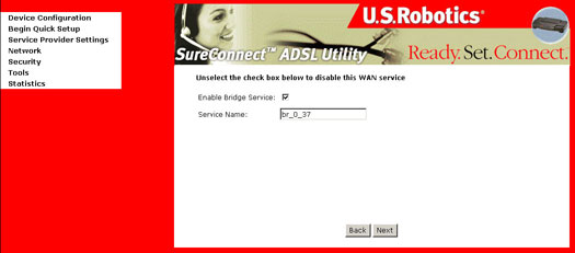
- Deselect Enable Bridge Service to disable ISP traffic on this service and click Next.
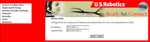
- Enter the IP address for
the LAN interface. The default IP address is 192.168.1.1. The LAN IP
interface in bridge operating mode is needed for local users to manage
the ADSL router.
Notice that there is no IP address for the WAN interface in bridge mode, and the remote technical support user cannot access the ADSL router. Click Next. - The Network Setup - Summary Screen presents the entire configuration summary. Click Finish to complete the configuration (which requires about 1 minute to complete) or Back to change any of the settings.
After having completed the Quick Setup, you should be able to browse the Internet and no additional configuration is needed.
Service Provider Settings
The DSL Settings dialog box allows you to select an appropriate modulation mode.
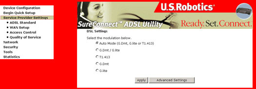
| Option | Description |
| Auto Mode (G.Dmt, G.lite or T1.413) | Sets the system auto-sense between G.Dmt, G.lite, or T1.413. |
| G.Dmt/G.lite | Sets G.Dmt/G.lite if you want the system to use either G.Dmt or G.lite mode. |
| T1.413 | Sets the T1.413 if you want the system to use only T1.413 mode. |
| G.Dmt | Sets the system to use only G.Dmt mode. |
| G.lite | Sets the system to use only G.lite mode. |
ADSL Standard Settings
This release supports ADSL2 connection. Check with your ISP to make use of this higher rate connection standad.
The DSL Advanced Settings dialog box allows you to select an appropriate test mode.
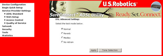
Warning!! These tones are for your ISP to perform DSL line testing. Running these tests may render your DSL service inoperable.
| Option | Description |
| Normal | Normal mode of operation. |
| Reverb | Send Reverb signal only. |
| Medley | Send Medley signal only. |
| No retrain | Stay in showtime even after the modem is disconnected. |
All three of these modes enable PSD measurements for each phase of training and showtime.
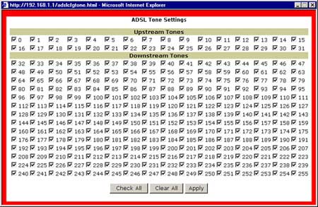
Tone Selection
The Tone Selection button prompts the ADSL Tone Settings dialog box. This allows you to select an appropriate number of upstream and downstream tones. Click Apply after you have made your selections.
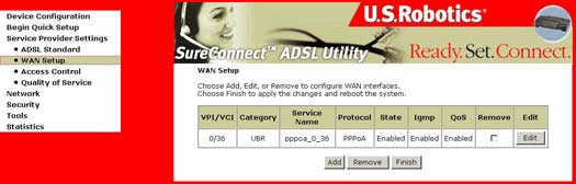
WAN Setup
The WAN Setup dialog box allows you to Edit or Remove your ISP configuration that was configured either by EasyConfigurator or during the Quick Setup step. Changes will take effect only after you choose Finish and reboot your router.
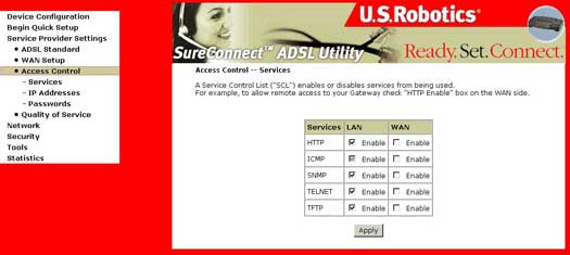
Access Control - Services
Select Services under the Access Control section. This screen allows for the control of device management to specify protocol for the LAN and WAN sides.
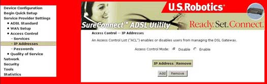
Access Control - IP Addresses
Select IP Addresses under the Access Control section. Select Disable or Enable here to either activate or deactivate the Access Control Mode (Device Management) by user's IP address. To add an IP Address to the list select Add. To remove an IP Address from the list, select Remove.
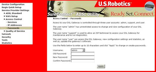
Access Control - Passwords
Select Passwords under the Access Control section. Use this screen to change or create Device Management passwords. When complete, click Apply.
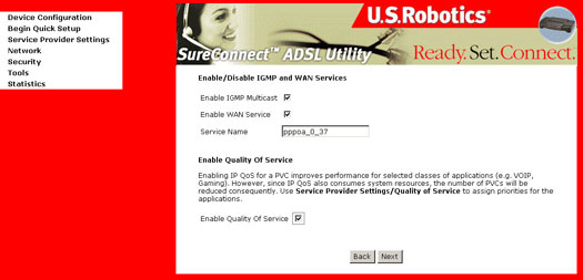
Quality of Service
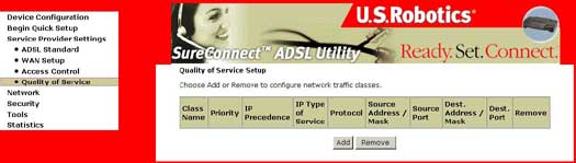
The Quality of Service (QoS) tab is useful only when all of the following conditions are met:
- PVC is not in bridge mode (that is, the WAN protocol can be in PPPoA, PPPoE, IPoA or MER)
- PVC is in set to one of
the following ATM service categories:
- UBR-with-PCR
- UBR-without-PCR
- non-realtime-VBR - There are enough ATM TX queues left in the system.
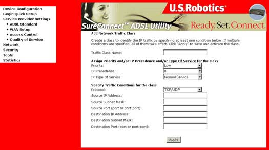
IP QoS is executed in the IP layer. It will classify traffic according to the classification rules. Each rule may contain a combination of the following conditions: protocol (TCP/UDP/ICMP), source IP address/subnet mask, destination IP address/subnet mask, source port (one or range), destination port (one or range). The result of matching a classification rule will produce a priority (high, medium, low) and a type of service (don�t care, Normal Service, Minimum Cost, Maximum Reliability, Maximum Throughput, Minimum Delay).
The IP Type of Service (TOS) of the matching rule will overwrite the original IP header TOS field if �don�t care� is not selected.
The priority of the matching rule determines which ATM TX queue to send over the PVC if the packet is routed to this PVC. The ATM SAR scheduler transmits the packet according to the following order:
- ATM service categorizes from the highest to lowest order: CBR, rt-VBR, rrt-VBR, UBR
- For the same service category: Priority level from high, medium, to low
- For the same priority level: round robin.
IP QoS will only take effect if the packet is routed to a QoS-enabled PVC. If it is routed to a regular QoS-disabled PVC, it will be transmitted at the same priority level as the low priority of a QoS enabled PVC of the same ATM service category.
Network
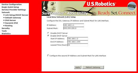
LAN Setup/DHCP Server
Configure the DSL Router IP Management Address and Subnet Mask for LAN interface and DHCP Server.
Default Gateway
The Default Gateway Configuration dialog box allows you to configure a static default gateway IP address.
If deselecting the Enable Automatic Assigned Default Gateway checkbox, the following screen appears:
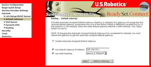
If you are configuring your router for either Routed Mode or Static MER Mode, you should enter a static Default Gateway IP Address in the corresponding field and use the appropriate WAN interface.
These settings will take affect only after you click Apply. If changing the Automatic Assigned Default Gateway from deselected to selected, you must reboot the router to get the automatically assigned default gateway.
DNS Server Configuration
The DNS Server Configuration dialog box allows you to configure a static DNS server IP Address.
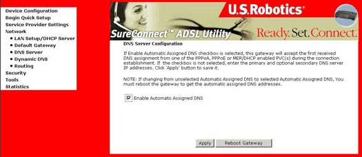
If deselecting the Enable Automatic Assigned DNS check box, the following screen appears:
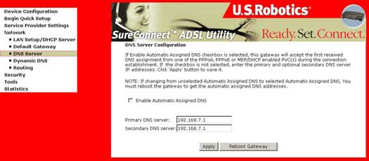
- If you are configuring your router for either Routed Mode or Static MER Mode, you should enter a static DNS server IP Address in the Primary DNS Server field. A secondary DNS server could also be entered.
- These settings will take affect only after you click Apply. If changing the Automatic Assigned DNS from deselected to selected, you must reboot the router to get the automatically assigned DNS address.
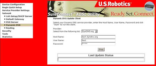
Dynamic DNS
DNS (Domain Name Service) is responsible for resolving an Internet name such as www.usr.com into an IP address for your ISP's equipment to find and serve you with it's Web contents. If we reverse the process, you use a Dynamic DNS Service. By registering with these Dynamic DNS Service providers, and programing your router, you router's public address will be resolved.
Routing
The Routing dialog box allows you to configure Static Route entry and static ARP entry.
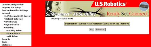
Pressing Add will open the following screen:
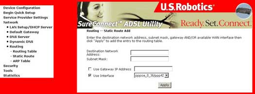
Routing Static Route Add
Pressing Add will open the following screen and you can add static routes
- Fill in data for:
- Destination Network Address and Subnet Mask
- Gateway IP Address
- Select the interface for which your settings apply
- Click Apply.
Routing ARP
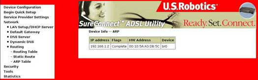
The MAC address has the following format "xx:xx:xx:xx:xx:xx" where xx are hexidecimal numbers.
Security
Firewall
Firewalls use one or more of three methods to control traffic flowing in and out of the network:
- Packet filtering: Packets (small chunks of data) are analyzed against a set of filters. Packets that make it through the filters are sent to the requesting system, and all others are discarded.
- Proxy service: Information from the Internet is retrieved by the firewall and then sent to the requesting system and vice versa.
- Stateful inspection: A newer method that doesn't examine the contents of each packet but instead compares certain key parts of the packet to a database of trusted information. Information traveling from inside the firewall to the outside is monitored for specific defining characteristics, then incoming information is compared to these characteristics. If the comparison yields a reasonable match, the information is allowed through. Otherwise, it is discarded.
IP Filtering-Outbound Filters
The firewall blocks internal users from accessing the Internet. There are two ways to accomplish this:
Using the TCP/UDP port to block internal users from accessing the Internet (also known as Port Filtering).
Using the IP address to block a specific user from accessing the Internet (also known as Address Filtering). The Firewall dialog box allows you to configure outgoing packet types to be sent using either TCP or UDP (or a combination of both) from specific ports.
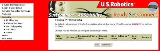
The following screen appears after you click Add.
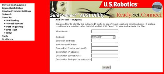
Firewall Outgoing - Port Filter Screen Fields
|
Option |
Description |
|
Protocol |
Selects TCP, UDP, or a combination of TCP/UDP. |
|
Source IP address (LAN) |
Enter the IP address you do not want to have access to the destination IP. |
|
Source Port (LAN) |
Enter the source port number, or range of ports, you want to block access (for source IP). |
|
Destination IP address |
Enter the IP address you do not want the source IP address to have access to. |
|
Destination Subnet Mask: |
Enter the subnet mask for the destination IP address. |
|
Destination Port (port or port:port) |
Enter the destination port number, or range of port numbers, you want to block access (for destination IP). |
IP Filtering - Inbound Filters
The screen allows inbound IP addresses to reach your computer. To add an IP address to the inbound filter list, click Add. To remove an IP address from the inbound filter list, click Remove.
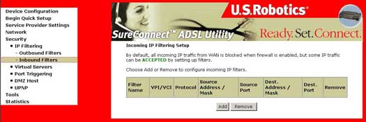
IP Filtering - Inbound Filters
|
Option |
Description |
|
Protocol |
Selects TCP, UDP, or a combination of TCP/UDP. |
|
Source IP address (WAN) |
Enter the IP address you want to have access to the destination IP. |
|
Source Port (WAN) |
Enter the source port number, or range of ports, you do not want to block access (for source IP). |
|
Destination IP address (LAN) |
Enter the IP address you want the source IP address to have access to. |
|
Destination Subnet Mask: |
Enter the subnet mask for the destination IP address. |
|
Destination Port (port or port:port) |
Enter the destination port number, or range of port numbers, you want to allow access (for destination IP). |
Network Address and Port Translation (NAPT)
Network Address and Port Translation (NAPT) allows a single device, such as a router, to act as an agent between the Internet (or "public network") and a local (or "private") network. This means that only a single, unique IP address is required to represent an entire group of computers.
Implementing dynamic NAPT automatically creates a firewall between your internal network and outside networks, or between your internal network and the Internet. NAPT only allows connections that originate inside the sub-domain. Essentially, this means that a computer on an external network cannot connect to your computer unless your computer has initiated the contact. You can browse the Internet and connect to a site, and even download a file; but somebody else cannot latch onto your IP address and use it to connect to a port on your computer.
Under the NAPT environment, all computers behind the NAPT are not accessible from outside (i.e., the WAN). However, if public services, such as web servers, ftp servers or e-mail servers, are needed from your private network, a virtual server can be configured to set up permit secured access. A virtual server setup enables a connection from outside to be redirected to a host running the services on the private subnet. This host running the services is called a virtual server (a virtual server is synonymous with IP forwarding).
The NAPT dialog box allows you to configure Virtual Servers and DMZ Host settings by adding, removing, and saving.
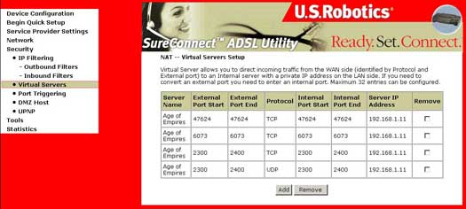
Virtual Servers
Selecting the Add button prompts the following screen:
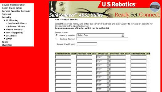
| Option | Description |
| Service Name | Allows the selection of an existing service from a drop-down-menu (web, FTP, e-mail). |
| Custom Server | Allows for an entry of a customer service where the name is known, but not listed in the Select a Service drop-down. |
| Server IP Address | The IP address of your computer that functions as a server. |
| Protocol | Allows the selection of a transport protocol (UDP, TCP, or both). |
| External Port (start/end) | Allows the entry of an individual external port or range of ports. |
| Internal Port (start/end) | Allows the entry of an individual internal port or range of ports. |
| Internal server IP address | The IP address of your computer that functions as a server. |
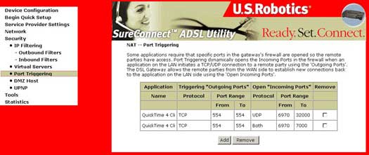
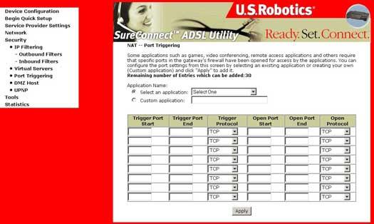
Port Triggering (also known as Port Forwarding)
Enter the application name, outgoing protocol, outgoing port range, incoming protocol, incoming port range, and click Apply to forward IP packets for this application to the specified ports.
DMZ Host
The DeMilitarized Zone (DMZ) Host option is used to forward IP packets from the WAN that do not belong to any of the applications configured in the virtual servers table, to the DMZ host computer. While virtual server can only forward (redirect) a limited number of services (ports), DMZ hosting allows all the services (ports) running on the DMZ host, to be accessible externally.
Selecting the DMZ Host button prompts the following screen.
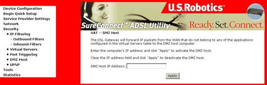
To configure the DMZ, type in the address of your computer that will function as a DMZ Host.
UPNP
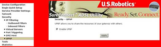
By default, UPNP is enabled. To disable, deselect Enable UPNP and click Apply.
Tools
Upgrade Gateway
The Update Software screen allows you to obtain an updated software image file from your ISP. Manual software upgrades from a locally stored file can be performed using the following screen.
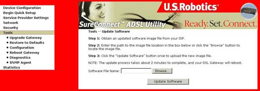
- Select the new image file after clicking Browse.
- Click Update Software. Completion of this step takes about two minutes. The 4-Port Router will reboot in the process.
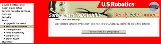
Restore to Defaults
The original factory installed settings can be restored by clicking the Restore Default Configuration option in the Restore Settings screen.
Default Settings
The 4-Port Router default settings are:
- Default network operating mode is Bridging.
- Default LAN port IP address is 192.168.1.1, subnet mask is 255.255.255.0
- Local User Name: admin
- Local User Password: admin
- Remote User Name: support
- Remote User Password: support
After the Restore Default Configuration button is selected, the following screen appears.
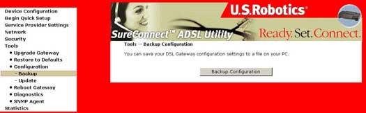
Configuration - Backup
To save your DSL Gateway configuration settings, click Backup Configuration and select a folder on your hard drive.
Note: You must have Explorer 6.0 or greater to successfully save your configuration settings.
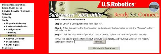
Configuration - Update
To update your DSL Gateway configuration settings, follow the steps provided on the screen.
Note: You must have Explorer 6.0 or greater to successfully update your configuration settings.
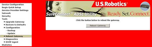
Reboot Gateway
The Reboot Gateway dialog box allows you to reboot the gateway. The reboot takes two minutes.
Diagnostics
The Diagnostics menu provides feedback on the connection status of the Wireless Gateway and the ADSL link. A description of each test can be obtained by clicking the Help button associated with the test.
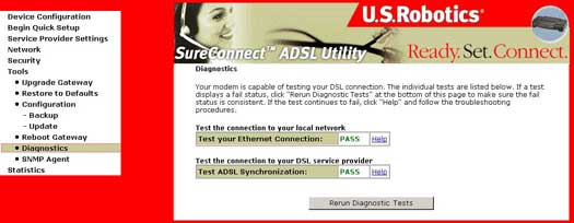
Without an active ADSL connection, many of the tests will not be activated, as shown in the following screen.
When the current network operating mode is in bridge, the default gateway and DNS server tests will not be activated.
Rerunning Diagnostics Tests
There are two buttons at the bottom of the screen:
- Rerun Diagnostic Tests
- Rerun Diagnostic Tests With OAM F4
When either of the Rerun Diagnostic Tests buttons are clicked, all the diagnostic tests are repeated. Normally, if one or more tests return a failure status, the user should rerun all the tests again to more thoroughly diagnose the problems encountered.
When you click Rerun Diagnostic Tests With OAM F4, ATM OAM F4 loopback cells are also transmitted, in addition to OAM F5 cells. It is possible that the ATM OAM F4 loopback or segment tests may not be supported by the ATM devices in the DSL service provider's network. For this reason, the OAM F4 test is separated from the general diagnostics tests. When an OAM F4 failure is encountered, the output screen will appear as an F4 Fail. The graphic below shows an example of diagnostics results when the PVC is configured in the PPPoE operating mode.
Diagnostic Test Description
| Test | Description |
| Ethernet Connection |
|
| ADSL Synchronization |
|
| ATM OAM Segment Ping |
The modem transmits OAM F4/F5 (if you rerun the test with OAM F4, both F4 and F5 are sent, otherwise only F5 is sent) segment loopback requests and expects a reply within 5 seconds. This test verifies that ATM continuity exists between the virtual channel link segment from the modem to the DSL provider network (typically this is a DSLAM at the DSL provider site).
|
| ATM OAM End-to-end Ping |
The modem transmits OAM F4/F5 (if you rerun the test with OAM F4, both F4 and F5 are sent, otherwise only F5 is sent) end to end loopback requests and expects a reply within 5 seconds. This test verifies ATM connectivity of the virtual channel link with the ATM PVC endpoint, such as a remote broadband access router located at the DSL provider or ISP site.
|
| PPP server |
For PPPoA operating mode, the modem checks if PPP (LCP and IPCP) is connected to the remote PPP server. For PPPoE operating mode, this test verifies that the modem can detect a PPPoE server by checking if it can receive a PADO (PPPoE Active Discovery Offer) packet from a PPPoE server after sending a PADI (PPPoE Active Discovery Initiation) broadcast packet.
|
| Authentication with ISP |
Verifies that the provided PPP username and password stored in the DSL modem have been authenticated by the PPP server within the ISP network.
|
| Assigned IP address |
Verifies that the DSL modem has a valid IP address (here, a PPP WAN IP address) from the PPP server.
|
| Ping default gateway |
|
| Ping Primary Domain Name Server |
Verifies that the DSL modem can communicate with the primary domain name server (DNS).
|
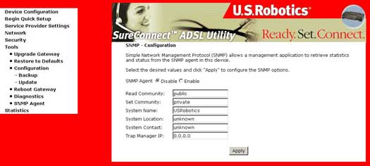
SNMP - Configuration
You can help your ISP troubleshoot the router by enabling this feature upon request from your ISP. It allows a management application to retrieve statistics and status from the SNMP agent in this device. If you enable this feature, you do not need to enable Remote Access for a management application to retrieve statistics and status from the router. The information entered in this screen should correspond with the information set in the management application.
Statistics
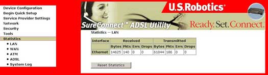
LAN
The LAN Statistics screen shows the byte transfer, packet transfer, and error statistics for the Ethernet interface.
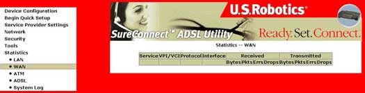
WAN
The WAN Statistics screen shows the byte transfer, packet transfer, and error statistics for the service settings.
ATM
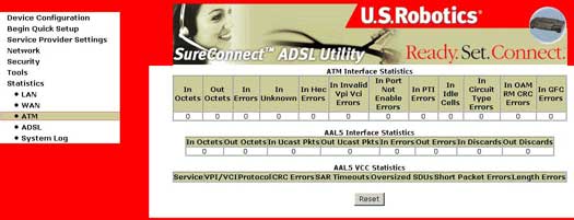
ATM Layer Statistics over ADSL interface
| Field | Description |
| InOctets | Number of received octets over the interface. |
| OutOctets | Number of transmitted octets over the interface. |
| InErrors | Number of cells dropped due to uncorrectable HEC errors. |
| InUnknown | Number of received cells discarded during cell header validation, including cells with unrecognized VPI/VCI values, and cells with invalid cell header patterns. If cells with undefined PTI values are discarded, they are also counted here. |
| InHecErrors | Number of cells received with an ATM Cell header HEC error. |
| InInvalidVpiVciErrors | Number of cells received with an unregistered VCC address. |
| InPortNotEnabledErrors | Number of cells received on a port that has not been enabled. |
| InPtiErrors | Number of cells received with an ATM header Payload Type Indicator (PTI) error. |
| InIdleCells | Number of idle cells received. |
| InCircuitTypeErrors | Number of cells received with an illegal circuit type. |
| InOamRmCrcErrors | Number of OAM and RM cells received with CRC errors. |
| InGfcErrors | Number of cells received with a non-zero GFC. |
ATM AAL5 Layer Statistics over ADSL Interface
| Field | Description |
| InOctets | Number of received AAL5/AAL0 CPCS PDU octets. |
| OutOctets | Number of AAL5/AAL0 CPCS PDU octets transmitted. |
| InUcastPkts | Number of received AAL5/AAL0 CPCS PDUs passed to a higher layer. |
| OutUcastPkts | Number of AAL5/AAL0 CPCS PDUs received from a higher layer for transmission. |
| InErrors | Number of AAL5/AAL0 CPCS PDUs received that contain an error. The types of errors counted include CRC-32 errors, SAR timeout errors, and oversized SDU errors. |
| OutErrors | Number of AAL5/AAL0 CPCS PDUs that could not be transmitted due to errors. |
| InDiscards | Number of AAL5/AAL0 CPCS PDUs discarded due to an input buffer overflow condition. |
| OutDiscards | This field is not currently used. |
ATM AAL5 Layer Statistics for each VCC over ADSL Interface
| Field | Description |
| CrcErrors | Number of PDUs received with CRC-32 errors. |
| SarTimeOuts | Number of partially reassembled PDUs which were discarded because they were not fully reassembled within the required time period. If the re-assembly timer is not supported, then this object contains a zero value |
| OverSizedSDUs | Number of PDUs discarded because the corresponding SDU was too large. |
| ShortPacketErrors | Number of PDUs discarded because the PDU length was less than the size of the AAL5 trailer. |
| LengthErrors | Number of PDUs discarded because the PDU length did not match the length in the AAL5 trailer. |
ADSL
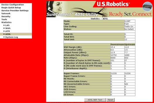
| Field | Description |
| Mode | Modulation protocol G.DMT or T1.413 |
| Type | Channel type Interleave or Fast |
| Line Coding | Trellis coding off or on |
| SNR Margin (dB) | Signal to Noise Ratio (SNR) margin |
| Attenuation (dB) | Estimate of average loop attenuation in the downstream direction |
| Status | Lists the status of the DSL link |
| Output Power (dBm) | Total upstream output power |
| Attainable downstream bit rate | Maximum achievable downstream rate |
| Rate (Kbps) | The rate at which data is flowing. |
| K | Number of data bytes in ADSL data frame (DMT symbol) |
| S | Length of Reed-Solomon code word in data frames |
| R | Number of redundant check bytes per Reed-Solomon code word |
| D | Interleaver depth |
| Super Frames | Total number of super frames |
| Super Frame Errors | Number of super frames received with errors |
| RS Words | Total number of Reed-Solomon code words |
| RS Correctable Errors | Number of RS words with correctable errors |
| RS Uncorrectable Errors | Number of RS words with uncorrectable errors |
| HEC Errors | Total number of Header Error Checksum errors |
| LCD Errors | Errors total number of Loss of Cell Delineation |
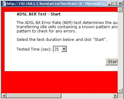
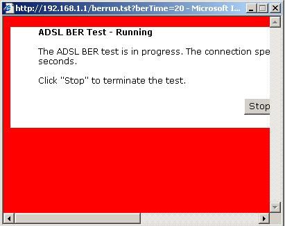
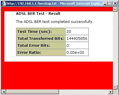
Within the ADSL Statistics window, a Bit Error Rate Test can be started using the ADSL BER Test button. The windows associated with this test include a start/configuration window, and in-process window and a results window.
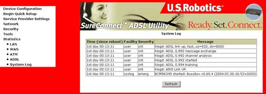
System Log
The System Log screen allows you to view the system events log or to configure the System Log options.
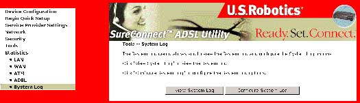
The System Log feature allows you to enable or disable System Log options.
- Click Configure System Log to display the following screen:
- Select from the desired System Log options, enter an option, then click Apply.
- Emergency = system is unusable
- Alert = action must be taken immediately
- Critical = critical conditions
- Error = error conditions
- Warning = warning conditions
- Notice = normal but significant conditions
- Informational = information events
- Debugging = debug-level messages
- Click View System Log. The results are displayed as follows:
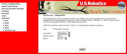
System Log - Configuration Options
| Option | Description |
| Log Status | Log Status indicates whether the system is currently recording events. The user can enable or disable event logging. By default, it is disabled. To enable it, click Enable and then Apply. |
| Log Level |
Log Level allows you to configure the event level and filter out unwanted events below this level. The events ranging from the highest critical level "Emergency" down to this configured level will be recorded to the log buffer on the Wireless Gateway SDRAM. When the log buffer is full, the newer event will wrap up to the top of the log buffer and overwrite the old event. By default, the log level is "Debugging," which is the lowest critical level. The following log levels are: Emergency is the most serious event level, whereas Debugging is the least important. For instance, if the log level is set to Debugging, all the events from the lowest Debugging level to the most critical level Emergency level will be recorded. If the log level is set to Error, only Error and the level above will be logged. |
| Display Level | Display Level allows the user to select the logged events and display on the "View System Log" page for events of this level and above to the highest Emergency level. |
| Mode | Mode allows you to specify whether events should be stored in the local memory or be sent to a remote syslog server, or both simultaneously. If "remote" mode is selected, view system log will not be able to display events saved in the remote syslog server. There are several types of syslog server software available for Windows and Linux operation systems. A free syslog server for Windows is Kiwi Syslog Daemon which can be obtained from www.kiwisyslog.com. When either Remote mode or Both mode is configured, the WUI will prompt the user to enter the Server IP address and Server UDP port. |
| Server IP Address | Field that appears when Remote or Both is selected in the Mode field. |
| Server UDP Port | Field that appears when Remote or Both is selected in the Mode field. Prompts the user to enter UDP port number of the SysLog server. A well known UDP port number, 514, is normally assigned to syslog. However, the user can overwrite with another UDP port number if a different UDP port is used by that particular syslog server. |